Using CCP Express Advanced Mode
This section explains how to configure Cisco IR routers using CCP Express advanced mode. The screens and configuration steps may slightly vary depending on the WAN configuration options and the software features supported by the Cisco IR routers.The Advanced Mode contains the following options:
■
■
■
■
■
■
■
■
■
■
■
■
CCP Express Home Page
Once the configuration is pushed, you will be automatically redirected to the Dashboard page in the Advanced Settings section.CCP Express by default loads in the New UI from version 3.5.1 onwards. User can switch back to the old UI by using the Option in Preferences-> Classic View. All existing features are arranged under 4 groups on the left: Dashboard, Configuration, Administration and Troubleshoot. The quick access utility pages/options are on the top right.
Figure 25 New UI in Release 3.5.1 and Later Releases

You can switch between the two UIs using the option in Preferences section.
Below are samples of the old UI.
Figure 26 CCP Express Home Page (IR 829)
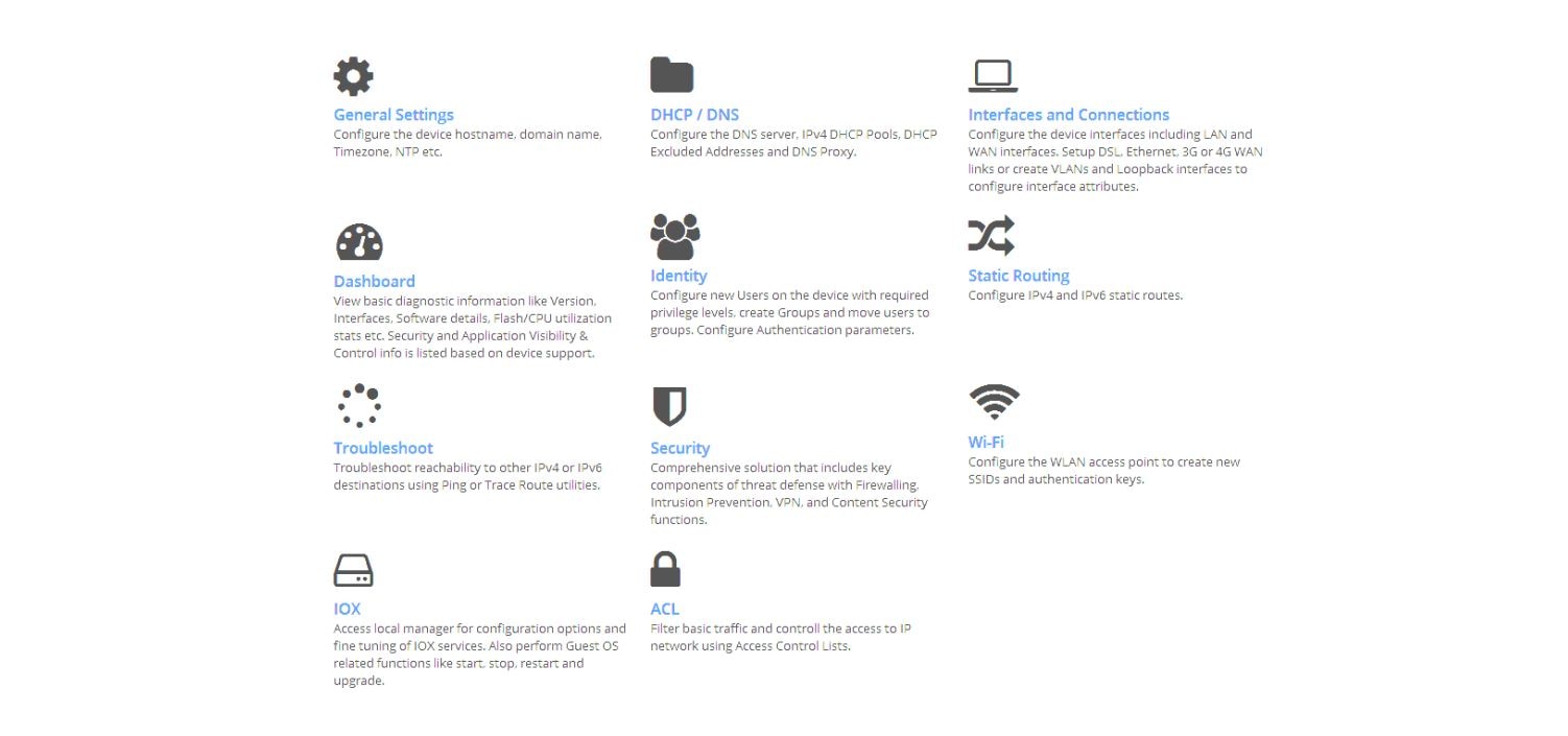
You can get to the CCP Express Home page by clicking on Advance Mode after going through the Quick Setup Wizard or by clicking the home icon on the right side of the page:
CCP Express Home Page (IR 829) shows CCP Express home page where you can navigate to all the features.
Note: Since the IR809 does not support Wi-Fi, the Wireless option is not available.
General Settings
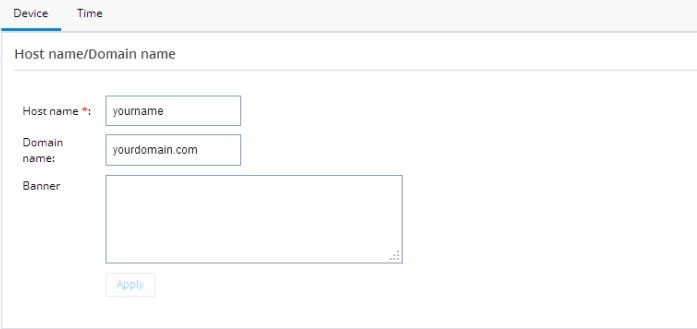
Click this option to configure Device and Time.If you used the Quick Setup Wizard to configure your router, the device settings shown in Device Settings are automatically listed here. If not, enter the Host name and Domain name.
Figure 27 Device Settings
Use the Time tab to change the timezone. You can also synchronize to the NTP server or make the router an NTP master.
Figure 28 Time Settings

SNMP Configuration
To enable SNMP configuration:1.
2.
All options are available under different tabs once SNMP is enabled on the box.
Figure 29 General SNMP Settings

Figure 30 SNMP Communities
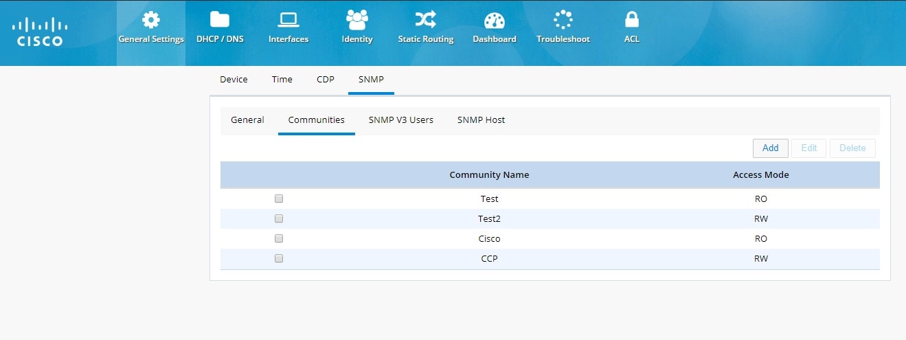
Figure 31 SNMP V3 Users

Figure 32 SNMP Host

Gyroscope
Gyroscope is used to determine the position of the device.1.
2.
Figure 33 Gyroscope
3.
4.
5.
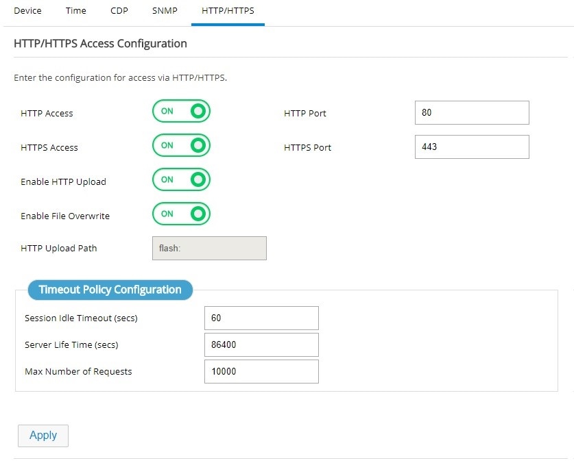
HTTP/HTTPS Configuration
Http/Https configuration is available under General Settings -> HTTP/HTTPS tab.Note: This feature is available in Release 3.5.1 and later.
Figure 34 HTTP/HTTPS Configuration

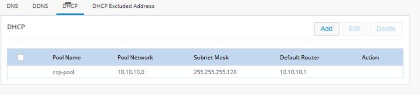
Configuring a LAN with DHCP
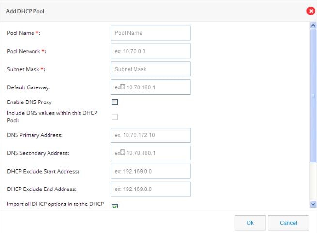
Perform the following steps to create a DHCP pool.1.
2.
■
■
■
■
Figure 37 Add DHCP Pool
3.
DHCP Excluded Addresses
To configure DHCP Excluded Addresses:1.
2.
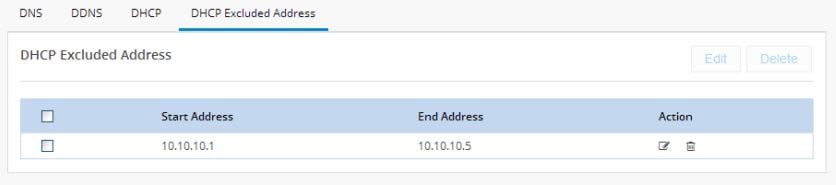
Figure 38 Configure DHCP Excluded Addresses
3.
To edit an existing DHCP Excluded Address:
1.
2.
Figure 39 Edit a DHCP Excluded Address
3.
4.
5.
To delete an existing DHCP Excluded Address:
1.
2.
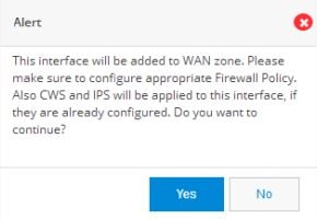
Interfaces
Use this option to configure primary and/or backup for Ethernet and Cellular interfaces.Figure 40 Interfaces List
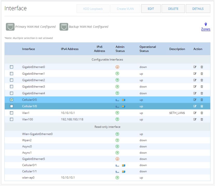
The Zones link takes you to the Zones page under the Security option. See The Zones Page.
Setting Up a Primary Ethernet WAN Interface
1.2.
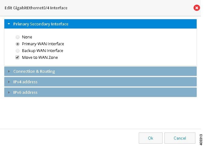
Figure 41 GigabitEthernet Interface Configuration
3.
4.
5.
6.
For configuring an IPv4 address:
This can be either Easy IP (IP Negotiated), Static IP Address, or No IP Address. By default, the IPv4 address is IP negotiated. There is an option to enable NAT configuration and the recommendation is to enable NAT for WAN interfaces. This will create NAT overloading configuration hence all LAN IPs are translated to public IP before being sent to WAN uplink.
For configuring an IPv6 address:
Select the IPv6 address type. The IPv6 address can be either AutoConfig, Use Prefix from Provider, Static IP Address, or No IP Address.
7.
8.
Setting up a Primary Cellular Interface
1.Figure 42 Edit Cellular Interface
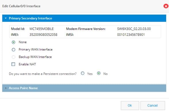
2.
3.
4.
5.
6.
7.
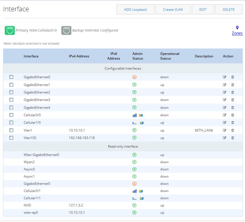
In the main Interfaces list, the Primary WAN Interface is green and lists the primary interface.
Figure 43 Configured Cellular Primary Interface
Setting up a Backup Cellular Interface
1.Figure 44 Edit Cellular Interface

2.
The SLA Configuration box displays.
3.
4.
5.
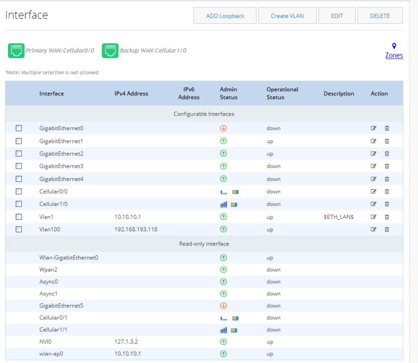
In the main Interfaces list, the Backup WAN Interface is green and lists the backup interface.
Figure 45 Configured Cellular Backup Interface
Create VLANs (only for IR 829)
Note: VLANs are not supported on IR 809.1.
2.
or
Select Static IP to assign a unique IP address to the VLAN.
3.
Identity
Identity awareness is a key requirement for any Security solution. It is defined as the ability of the device to be aware of end-user identities. Also this supports User and Group management that allows administration of user authentication and authorization profiles using either local or external service.Authentication
To configure authentication:1.
2.
–
–
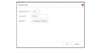
If remote option is selected, the ADD new server option appears.
a.
b.
Note: You can choose to configure both the server options. If both are configured, first attempt with authentication is with the remote server. If the remote server is not reachable, authentication falls back to the local server.
3.
The authentication method can be chosen for different zones, but in the current release only LAN zone is supported. If LAN Zone is configured, all interfaces coming under LAN zone are configured accordingly. NTLM option is supported only for remote server option. If the you configure both on-box and remote server options, selecting NTLM option is not allowed.
Figure 46 Authentication Page
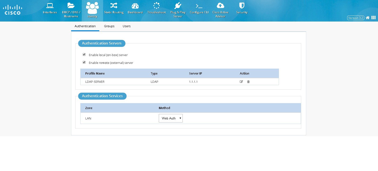
Figure 47 Add/Edit LDAP Page
Managing User Groups
To create or delete user groups or to see the list of created user groups:1.
2.
3.
Figure 48 Group Management Page
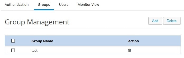
4.
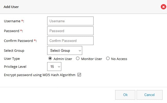
Managing Users
Steps to create a new user and associate/dissociate a user with a group are listed below:1.
2.
3.
Figure 49 User Management Page
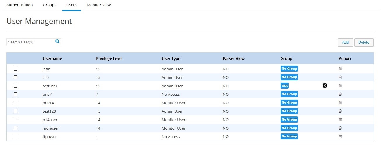
Figure 50 Add User Page
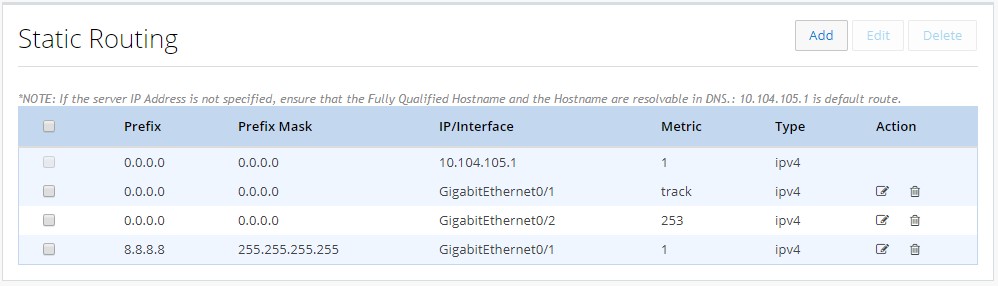
Creating a Static Route
To create a static route:1.
Figure 51 Static Routing
2.
Figure 52 The Static Routing page
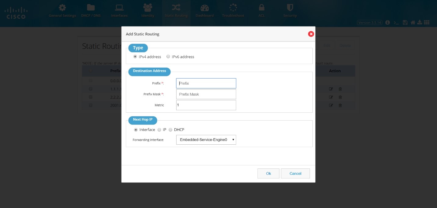
3.
■
■
If you select Interface as the next hop IP, select the forwarding interface from the drop-down list.
If you select IP as the next hop IP, specify the Next Hop IP that must be used.
You can also specify DHCP address.
4.
Editing a Static Route
To edit an existing static route:1.
2.
The Edit Static Routing page is displayed.
3.
■
■
If you select Interface as the next hop IP, select the forwarding interface from the drop-down list.
If you select IP as the next hop IP, specify the Next Hop IP that must be used.
4.
Deleting a Static Route
To delete a static route:1.
2.
Dashboard
The Dashboard view shows the vital hardware health status of the router along with the flash and system memory, CPU utilization, and WAN Interface status and security aspects of network. The Dashboard has two sections Router and Security.Viewing Router Dashboard
To view the router diagnostics using the dashboard view, perform these steps:1.
The Dashboard page
Hardware Health section shows the total Power Consumption of the router, Number of Fans on the system and their status, CPU Temperature and Battery health. If the router does not expose its hardware information, then this section will not be visible in the UI.

If Primary and Backup WAN Interfaces are configured, then the status of the same is displayed along with the interface Name. The status is shown in green only when both admin and operational status are up. This also shows the amount of traffic flowing through WAN Interfaces.
Note: The following sections have been moved to the System Information Popup: Hostname, Device Type, IOS Version, System Uptime from last reload, current System Time, and the Reason for Last Reload of the router. The Interfaces chart is moved under the Interfaces tab.
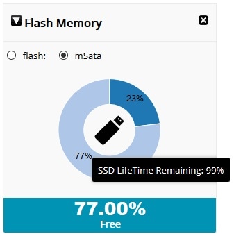
Beginning with CCP Express Release 3.5.2, for IR829M series devices, the Flash Memory dashlet will display two radio buttons: “flash” and “mSata.” The flash option retains the current dashlet data which is the pie chart that shows used and free space on the flash memory. If you select the mSata option, the used and free data of the SSD is displayed. You can hover on the flash icon and get the remaining lifetime for the SSD also.
Figure 53 Flash Memory Dashlet
2.
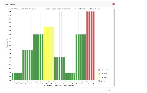
CPU Utilization Dashlet
To access the new CPU Utilization dashlet:1.
2.
A new dashlet is shown in a popup dialog. The details of CPU usage are in percents for different intervals available in the new dashlet.
Security Dashboard
To view the security dashboard view, perform these steps:1.
Figure 54 Security Dashboard (Dashlets displayed are Top 10 Applications and Top Users)
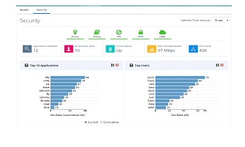
Figure 55 Security Dashboard (Dashlets displayed are VPN, Policy, Top 10 Threats and IPS Drilldown)
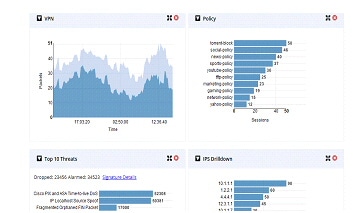
Figure 56 Security Dashboard (Dashlets displayed are Firewall Drop and CWS Connections)

The top portion shows the security features enabled on the device. The green icon indicates they are enabled. User can click on a specific icon and navigate to that feature. If any security feature is not enabled, then the relevant charts are not visible. They will be minimized and shown in the tray above the pane which is showing the security features ennoblement status. To close any chart click on the close button of the chart and the chart will be minimized into the tray. The icons can be clicked to enable it again.
Security Snapshot
■■
■
■
■
Security Charts
Following is the list of various charts supported to show the security information and bandwidth consumption statistics of the network. These charts will update periodically. The refresh interval can be modified.■
■
■
■
■
■
■
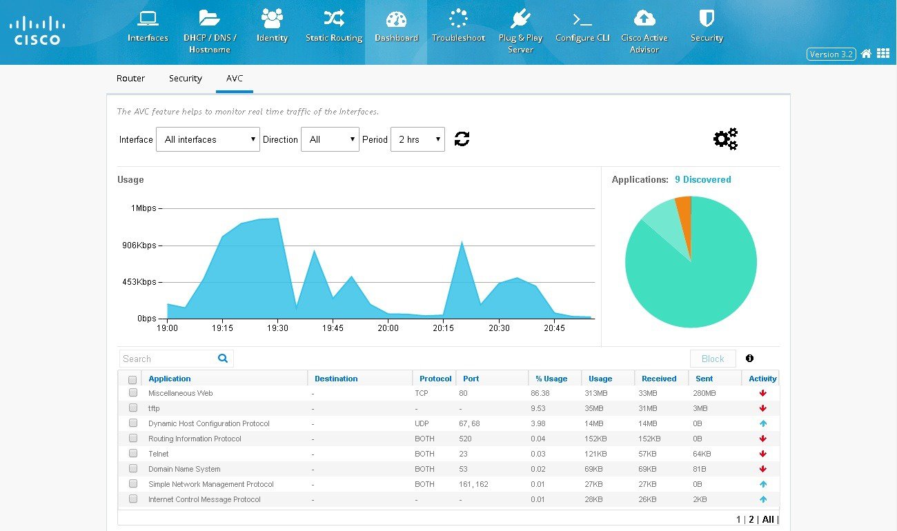
Application Visibility and Control (AVC) Dashboard
To view the AVC dashboard, perform these steps:1.
2.
Figure 57 Configuring AVC
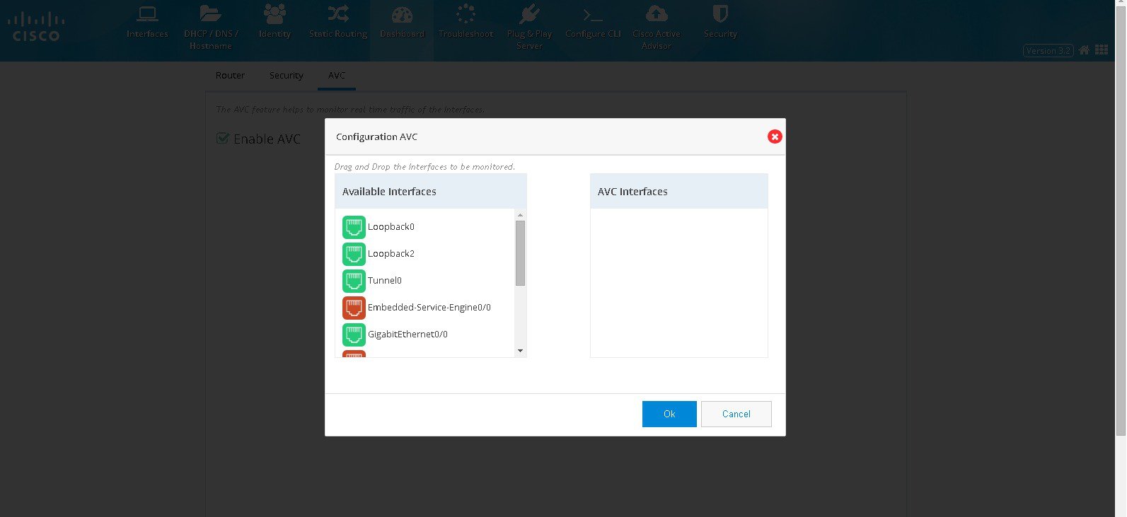
3.
Figure 58 AVC Dashboard
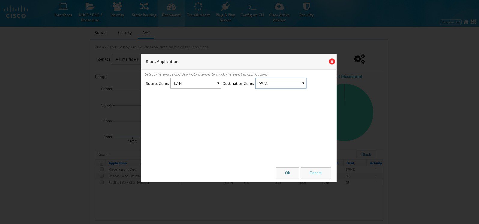
4.
5.
Figure 59 Blocking Applications
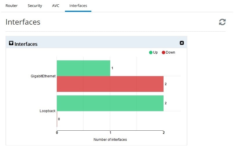
Interfaces Dashboard
To view the Interfaces dashboard, perform these steps:1.
Interfaces chart groups the Interfaces by type and shows the number of interfaces that are up and down. If the user moves the cursor over the chart, then the specific interfaces will be displayed as tool tip.
Figure 60 Interfaces Dashboard
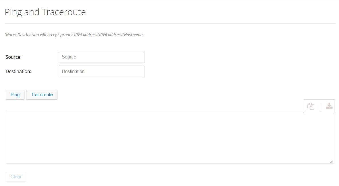
Ping and Traceroute
The Ping and Traceroute utility allows you to do a basic troubleshooting of the network and device connectivity.To troubleshoot the device connectivity, perform these steps:
1.
Figure 61 Ping and Traceroute
2.
3.
4.
5.
6.
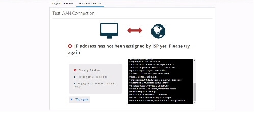
Test WAN Connection
If you do not have a primary interface configured, the following message appears: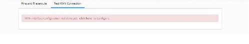
If a primary interface is configured without an IP address, the following information appears:
If a primary interface is configured with an IP Address and DNS details, the following information appears:
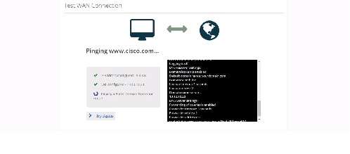
For a successful connection, the following information appears:

Access Control Lists (ACLs)
Filter traffic and control access to the IP network using the ACL option from the main menu.Figure 62 ACL Summary
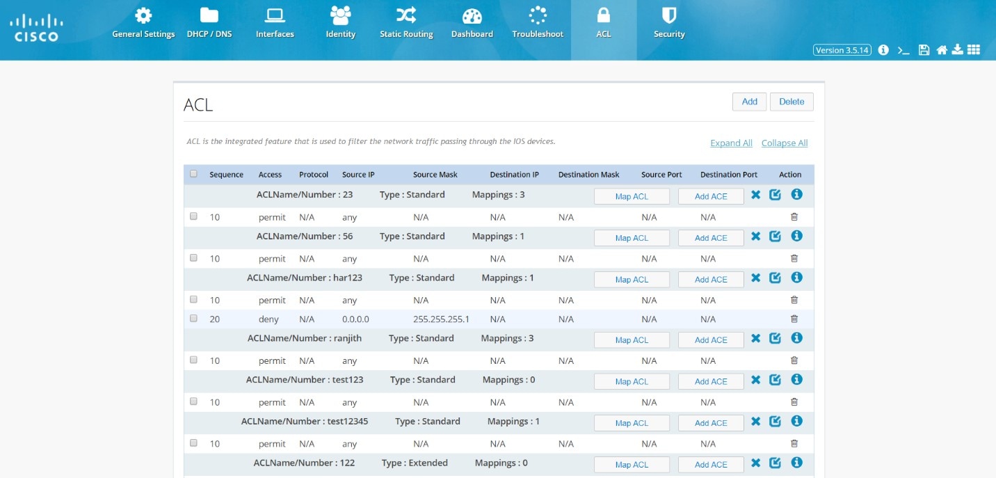
This page includes the Map ACL and Add ACE buttons for each ACL. Hover over the icons on the right to remove an ACL, expand and collapse an ACL.
Add an ACL
To add an ACL:1.
Figure 63 Add ACL
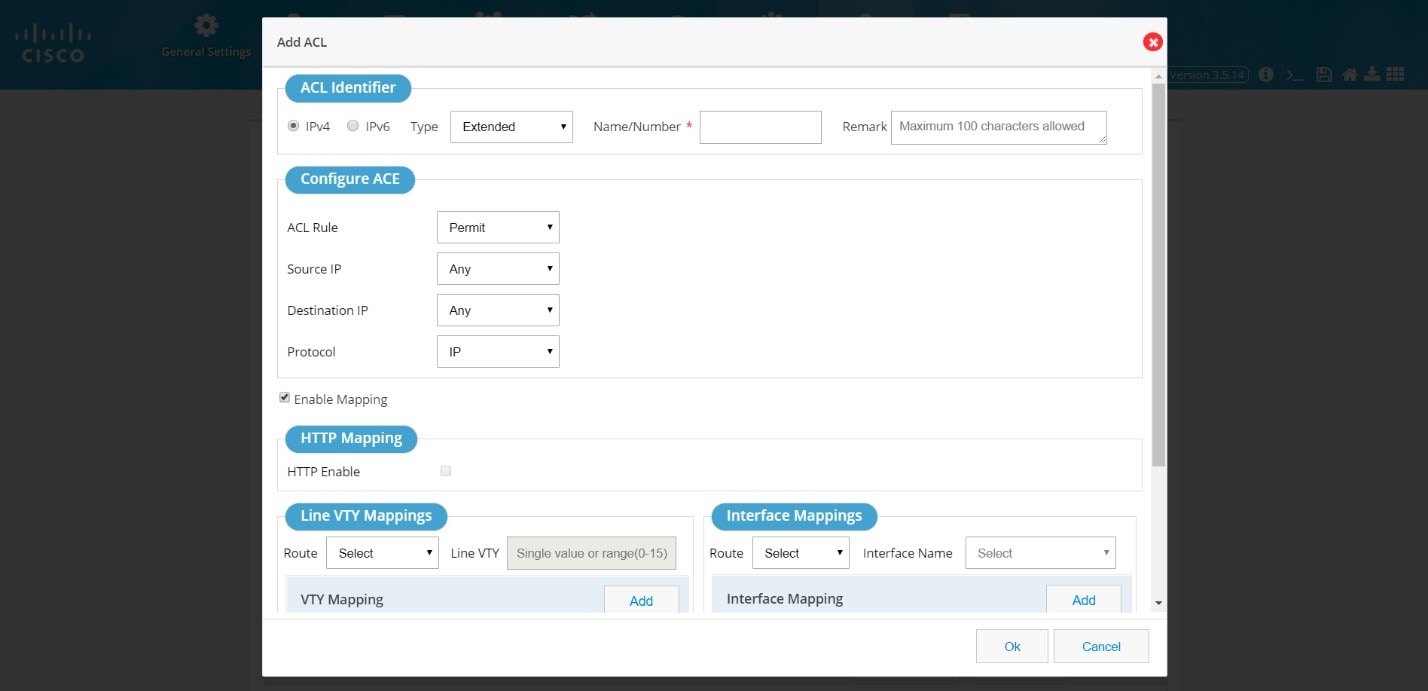
2.
3.
4.
You can also add mappings while adding the ACL through this window.
Add an Extended ACL
1.2.
Figure 64 Add an Extended ACL
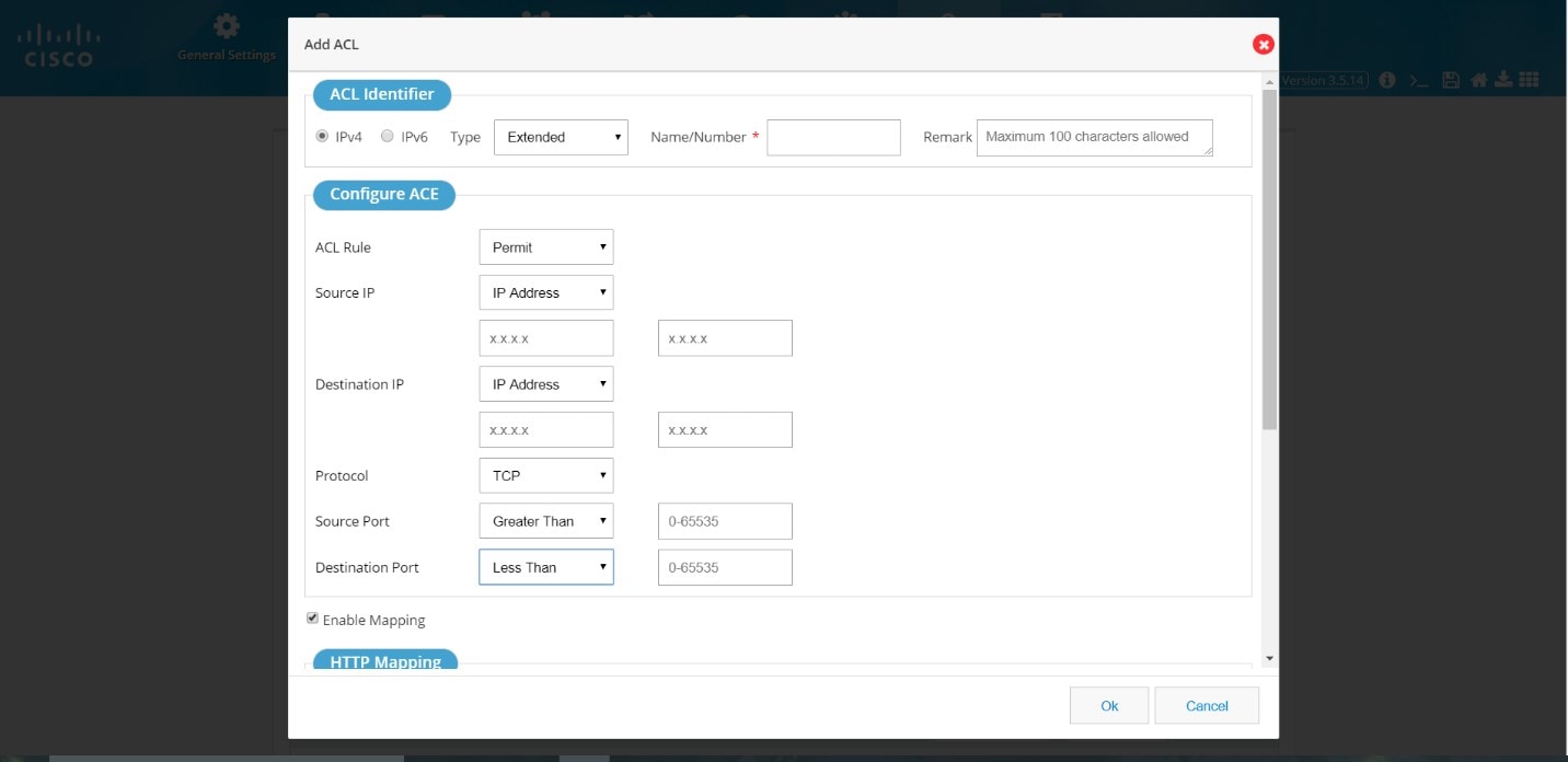
3.
Map an ACL
To map an ACL:1.
Figure 65 Map ACL
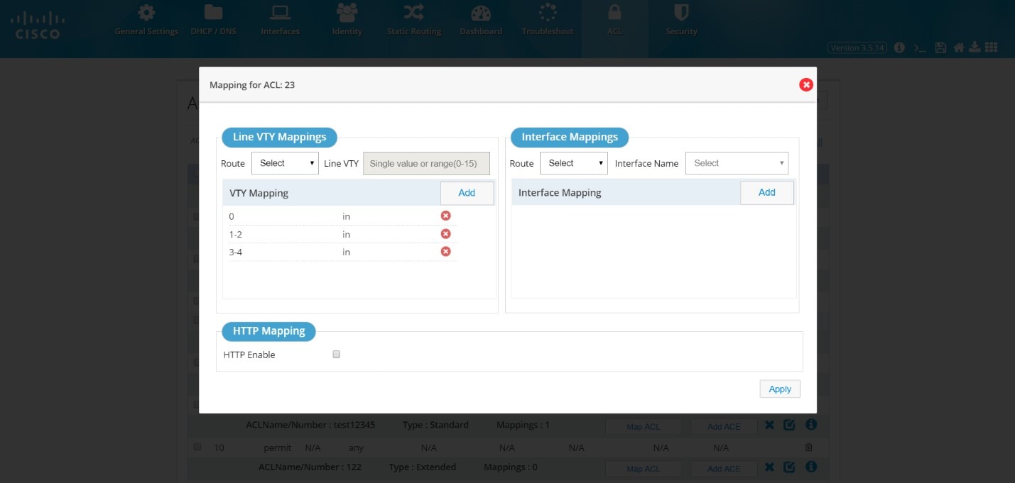
2.
or
Select the VTY route, and add the VTY value.
Note: HTTP option will be enabled only for Standard numbered ACL.
IOx
Use this option to access IOx services through the local management interface.If IOx is not configured on the router, the following message displays:

After you configure IOx on the router, select IOx from the Home menu.
Depending on your configuration, you can access IOx Manager through LAN or WAN.
Click either option to launch the Local Manager.
Figure 67 IOx Management

Guest OS Functions
Use this window to start, stop, or restart Guest OSFigure 68 Guest OS Stopped
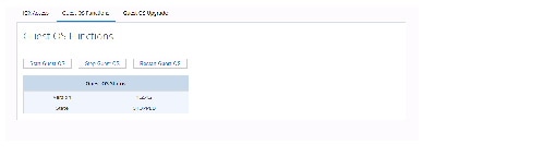
Figure 69 Guest OS Start

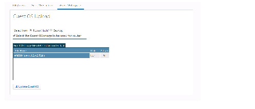
Guest OS Upgrade
1.2.
3.
Figure 70 Guest OS Upgrade

4.
5.
If you do not have a Cisco.com login, ensure you register.
After you upload the file, the following message displays:

6.
7.
8.
Once the upload is completed, the application automatically comes back to the Guest OS Update main page which lists all the available IOS images on the router.
9.
10.
Figure 71 Guest OS Upload Completed
For more information about IOx, refer to the IOx documentation at the following URL:
http://www.cisco.com/c/en/us/support/cloud-systems-management/iox/tsd-products-support-series-home.html
Wireless
Wireless configuration is done through the Wi-Fi Manager which is external to CCP Express.When you click Wi-Fi, you receive the following message with a link to Wi-Fi Manager:
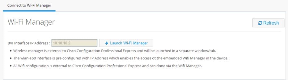
1.
2.
Figure 72 Wi-Fi Manager (External to CCP Express)
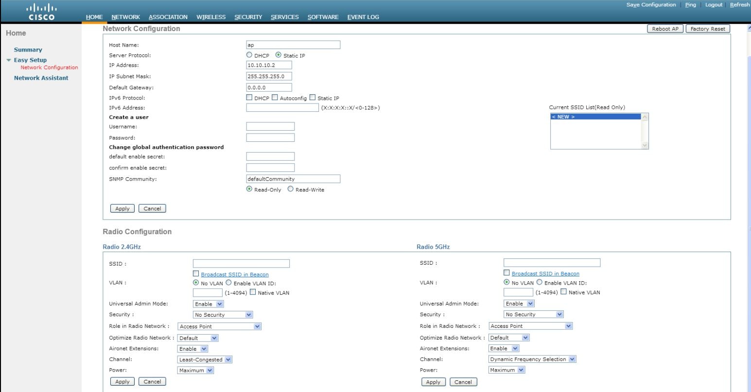
For more information about configuring access points, refer to the Cisco IOS Configuration Guide for Autonomous Aironet Access Points documentation at:
http://www.cisco.com/c/en/us/td/docs/wireless/access_point/15_2_4_JB/configuration/guide/scg15-2-4-Book.html
3.
The SSID can contain up to 32 alphanumeric characters.
4.
When you broadcast the SSID, devices that do not specify an SSID can associate with the access point. This is a useful option for an SSID used by guests or by client devices in a public space. If you do not broadcast the SSID, client devices cannot associate to the access point unless their SSID matches this SSID. Only one SSID can be included in the access point beacon.
5.
This will enable the clients that connect to the SSID to use the IP addresses from the DHCP pool associated with this VLAN.
6.
■
■
7.
The SSID appears in the SSID table on the bottom of the page.
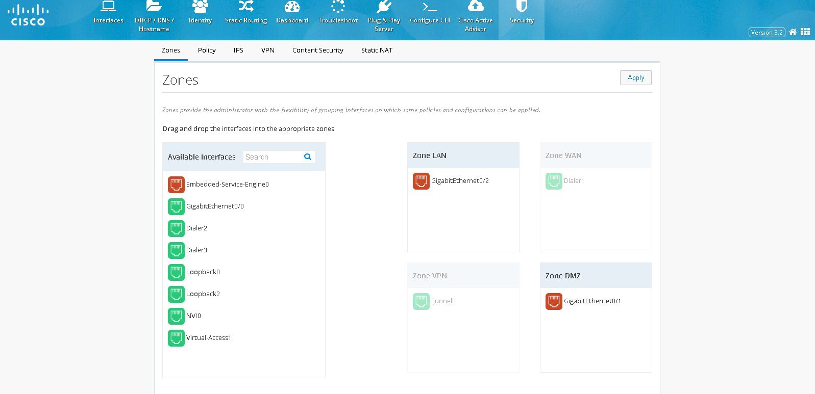
Zones
Zones establish the security borders of your network. A zone defines a boundary where traffic is subjected to policy restrictions as it crosses to another region of your network. ZFW’s default policy between zones is deny all. If no policy is explicitly configured, all traffic moving between zones is blocked.■
■
Figure 73 The Zones Page
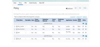
Policy
With the Zones and Policy pages configured, users can enable Zone based Firewall on the device. Policy page applies user-defined rules or policy on the traffic that flows between source and destination zones. The source and destination zones are tied together to make a zone pair under which the policy is applied. Prior to creating and applying policy, user needs to configure and assign the interfaces under the right zones.Policy feature provides more granularity in identifying and filtering the traffic. Within the traffic between source zone and destination zone, the user can filter the traffic further based on the source and destination network, application type, the source and destination ports, domains, and the user groups.
Policy Summary
To view the policy summary, perform these steps:1.
–
–
Figure 74 The Policy Page
Prerequisite for Creating Any Policy
■
■
Some sample use case scenarios are explained below
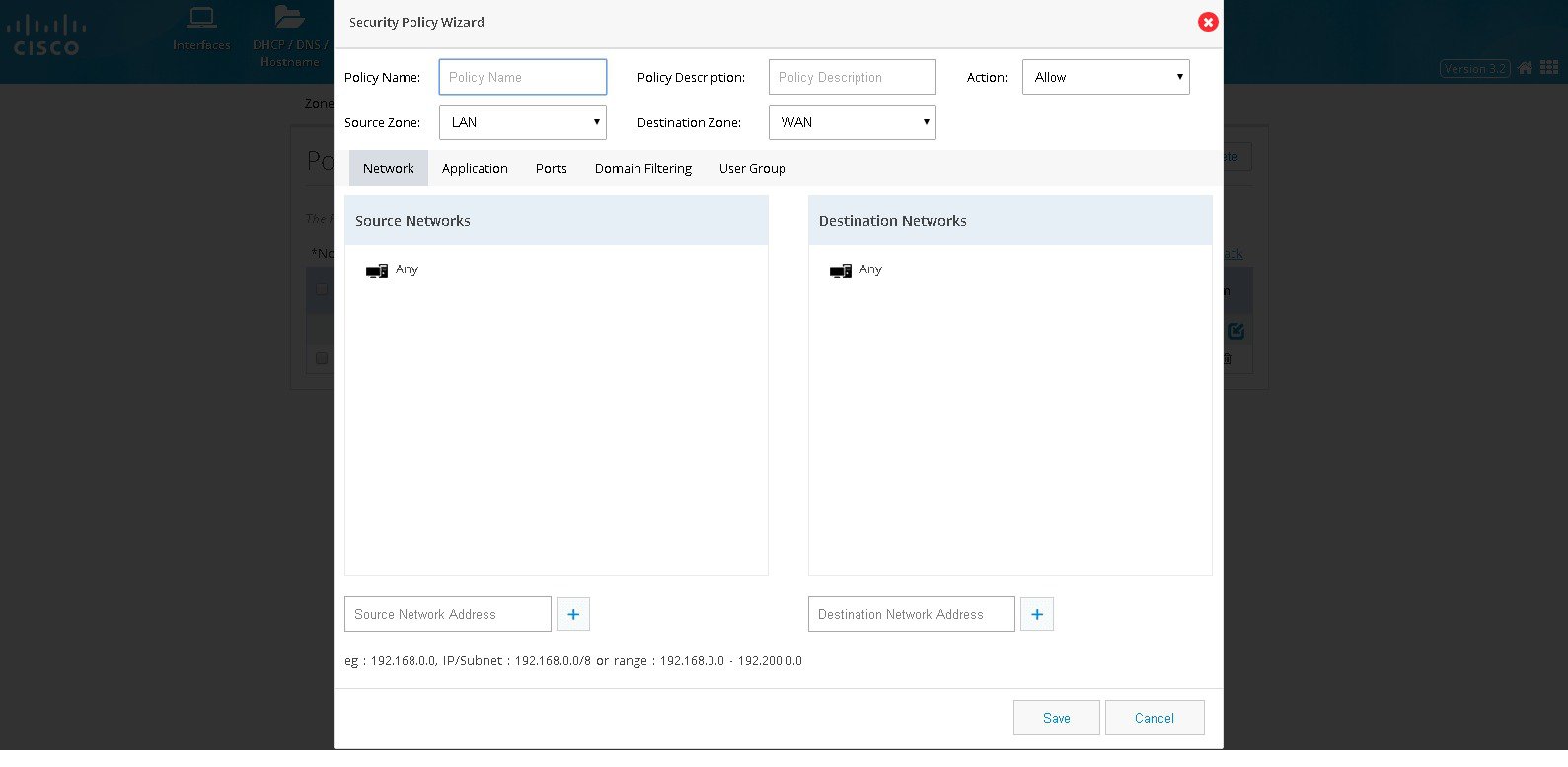
Block a Specific Application
To block a specific application, perform these steps:1.
2.
3.
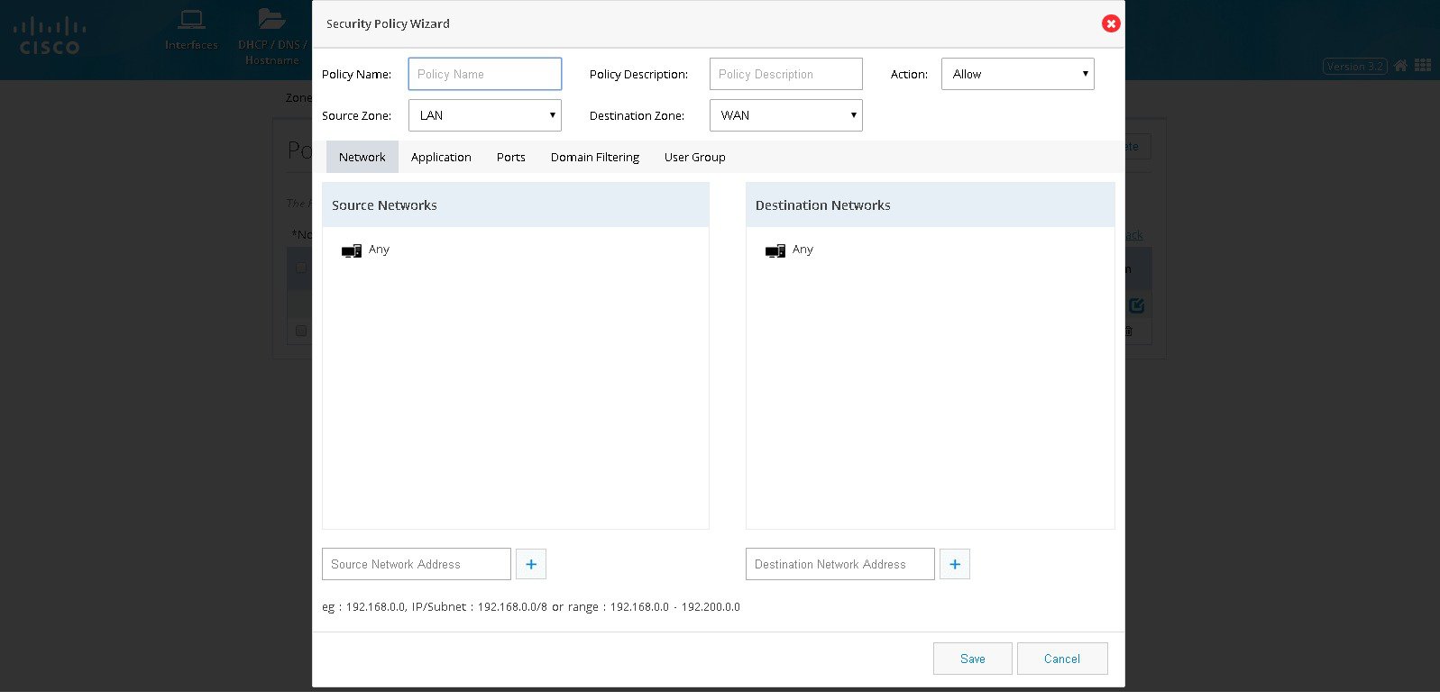
Figure 75 The Security Policy Wizard (Landing screen with Network tab contents)
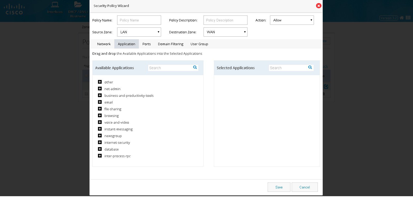
4.
Figure 76 The Security Policy Wizard (Application tab contents)
5.
Figure 77 The Security Policy Wizard (Ports tab contents)
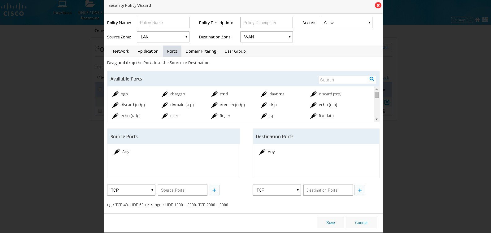
6.
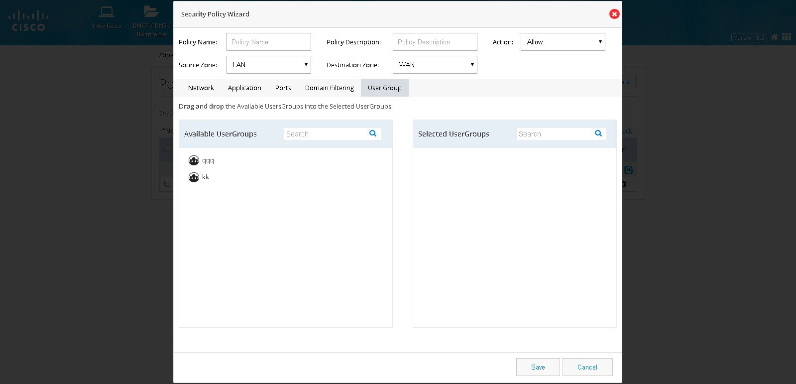
Figure 78 The Security Policy Wizard (User group tab contents)
Block a Specific Domain
To block a specific domain, perform these steps:1.
2.
3.
Figure 79 The Security Policy Wizard (Landing screen with Network tab contents)
4.
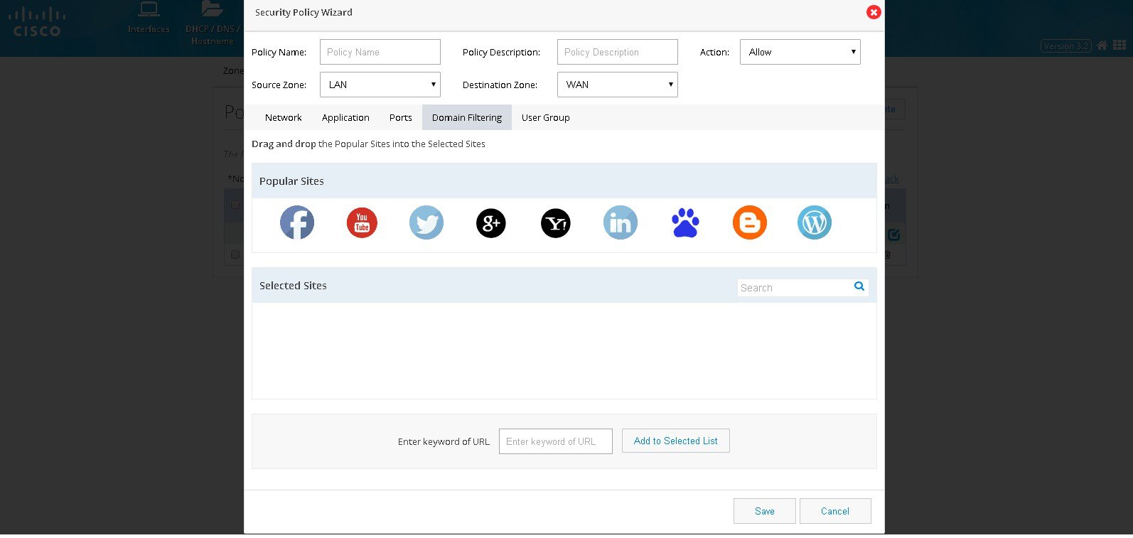
Figure 80 The Security Policy Wizard (Domain Filtering tab contents)
5.
Note: To select the specific User group it should have been already added through the Identity feature.
IPS
Cisco IOS Intrusion Prevention System (IPS) is an inline, deep-packet inspection feature that effectively mitigates a wide range of network attacks. A component of the Cisco IOS Integrated Threat Control framework and complemented by Cisco IOS Flexible Packet Matching feature, Cisco IOS IPS provides your network with the intelligence to accurately identify, classify, and stop or block malicious traffic in real time.Prerequisites for Using IPS
■■
■
If these conditions are not met, respective error messages are displayed when the IPS feature is accessed.
Enabling IPS
If all the prerequisites are met, you receive the option to enable IPS.1.
2.
Figure 81 IPS Signatures
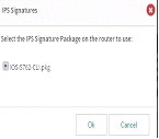
3.
4.
Figure 82 Intrusion Prevention System Page
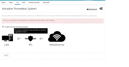
5.
6.
Note: For all further disable/enable cycles, you are not prompted to select the package. In those cycles, after enabling, you get a message that “Signature compilation is in progress”. You can choose to visit other pages and come back later or to hit “Refresh” after a while to see the IPS settings screen.
Uploading IPS Signature Packages
You have the option to upload signature packages onto the router at any point in time. To upload IPS signature packages, perform these steps:1.
2.
3.
CCP Express validates for the file name, duplication and free space on the router. If any of these validations fail, appropriate error message are displayed. If the file validations are completed, you receive the message that file is ready for upload and the “Upload” button is enabled.
4.
Upload takes a while as the file size is around 20MB. You are notified when the upload is completed. You can upload more files or quick the dialog.
Changing IPS Signature Packages
When IPS is enabled, if the box has more than one Signature Package file, you are provided with an option to change the signature package. To change IPS signature packages:1.
2.
A dialog box with the list of available packages on the box is displayed. The currently selected one is listed, but selection is disabled for this one. The packages are sorted in reverse alphabetical order to have the latest one at the top for easy selection.
3.
4.
Download Link for IPS Signature Packages
You can download the relevant signature package files from the link that is shared with you. This is a link that connects you to an internal CISCO page. To download IPS signature package:1.
2.
Enabling/Disabling Notifications/Log
You are provided with links to enable and disable SDEE and syslog notifications. The menu is smart to toggle between the enable and disable options for each based on the setting in the system.SDEE Notifications
To enable SDEE notifications:1.
2.
3.
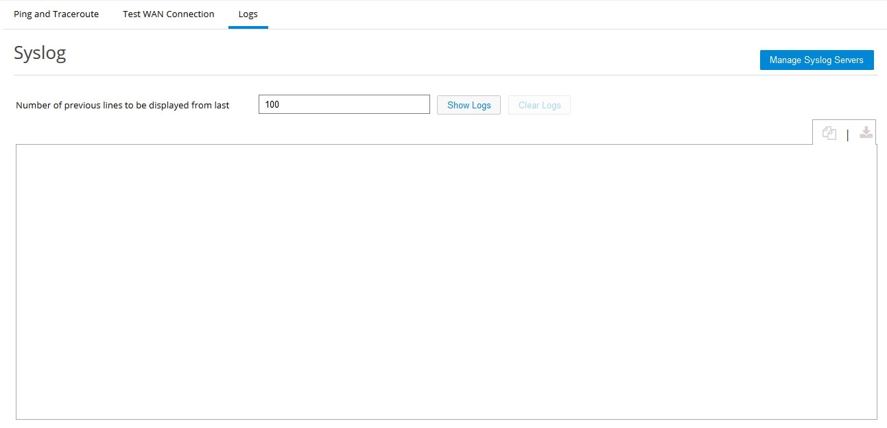
Syslog
Use this section to check the Syslog on the device. This feature is available in CCP Express Release 3.5.2 and later releases.To enable Syslog:
1.
Figure 83 Syslog View
2.
Figure 84 Syslog - Show Logs
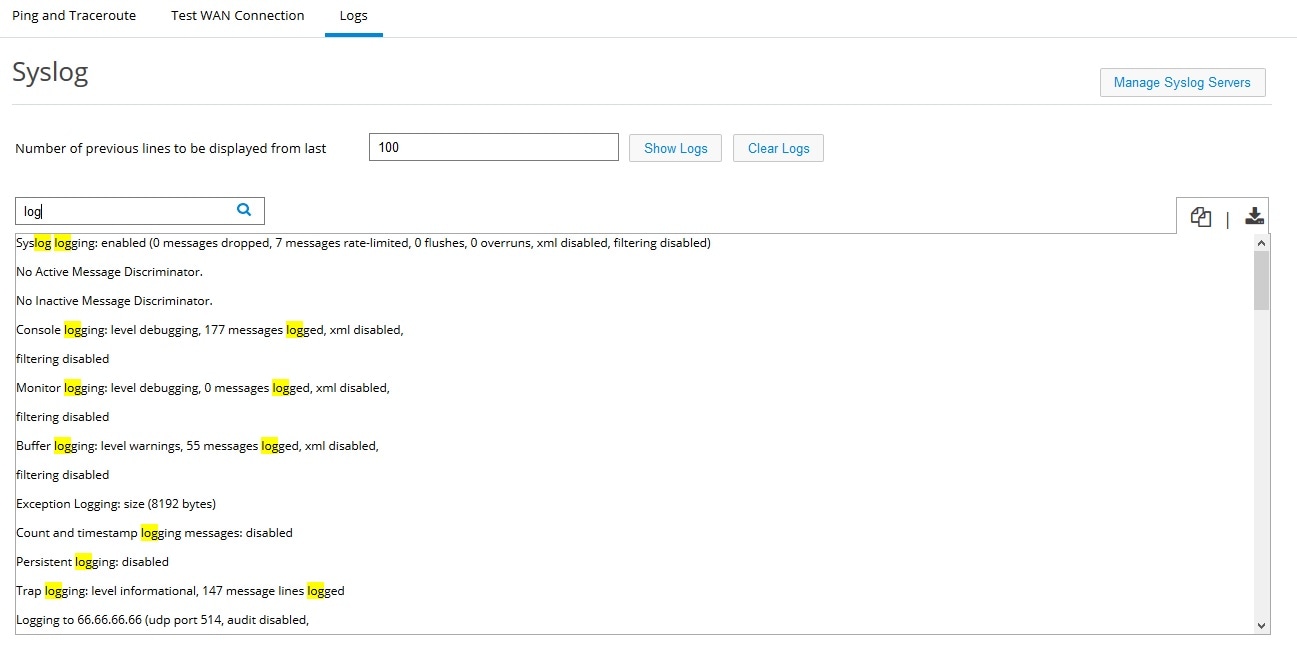
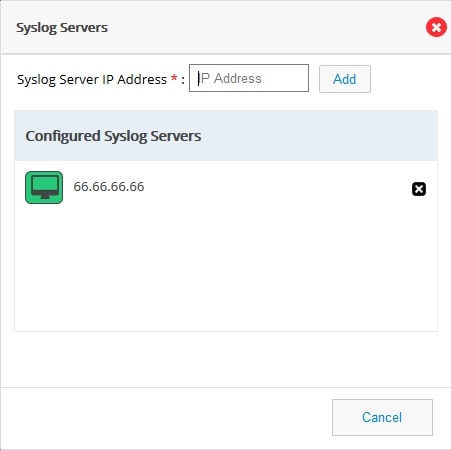
3.
Figure 85 Syslog Servers
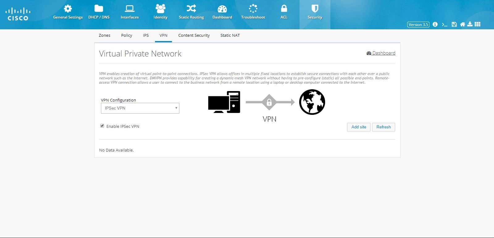
VPN
CCP Express supports creation of IPSec multi-site VPN configuration, DMVPN spoke side configuration, DMVPN hub configuration, remote access configuration, a combination of IPSec multi-site with remote access configurations, and a combination of DMVPN hub with remote access VPN configurations.Prerequisite for VPN
Primary WAN interface must be configured and should be part of WAN Zone. Also, LAN interfaces should be part of LAN Zone before configuring any VPN.IPSec Multi-Site Configuration
To configure multi-site VPN:1.
2.
Figure 86 IPSec Multi-Site VPN
3.
Figure 87 IPSec Multi-Site VPN (Tunnel Configuration)

Note: By default, from configuring site end, all the LAN side networks are allowed to access the other end through VPN tunnel.
4.
Figure 88 IPSec Multi-Site VPN (Remote Configuration)
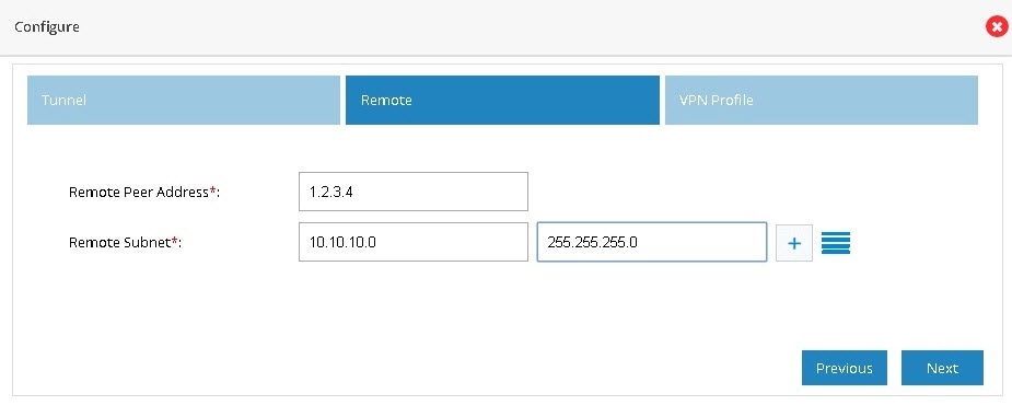
5.
6.
Figure 89 IPSec Multi-Site VPN (Profile)
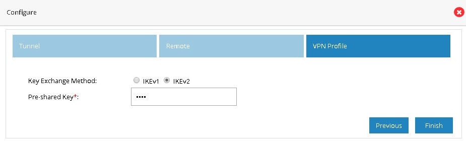
7.
Figure 90 IPSec Multi-Site VPN (Advanced Options)
8.
After the configuration is complete, the list of sites is displayed. You can choose to add more or delete sites from the available list.
Figure 91 IPSec Multi-Site VPN (Completed)
Note: If CCP Express is used to configure the Multi-Site VPN, ensure that both the ends are configured with CCP Express only. CCP Express internally uses the transform set as esp-aes, esp-sha-hmac and IKEv2 Proposal with encryption as 3des, integrity as md5 and Diffie Helman group as 2.
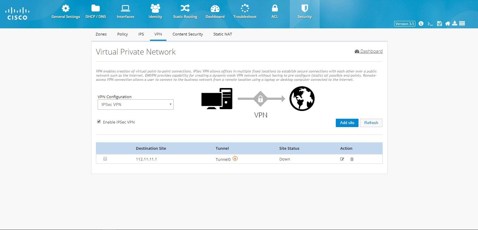
DMVPN Spoke Configuration
To enable DMVPN Spoke configuration:1.
2.
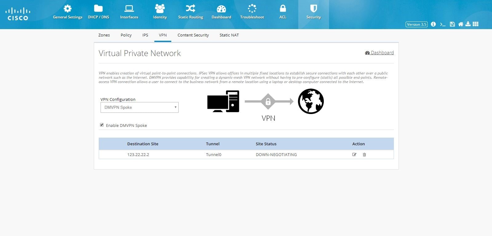
Figure 92 DMVPN Spoke Configuration

3.
4.
Figure 93 DMVPN Spoke Configuration (VPN Peers)
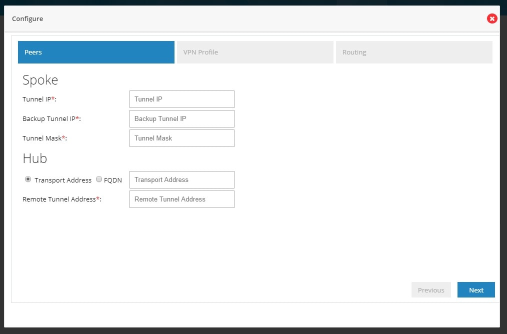
By default from configuring site end all the LAN side networks are allowed to access the other end through VPN Tunnel.
When DMVPN Spoke configuration is successfully completed, and the Hub is configured and active, the tunnel will come up between Hub and Spoke.
5.
6.
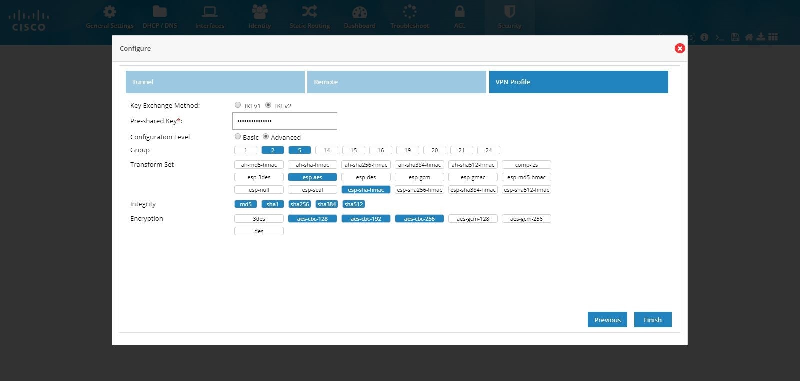
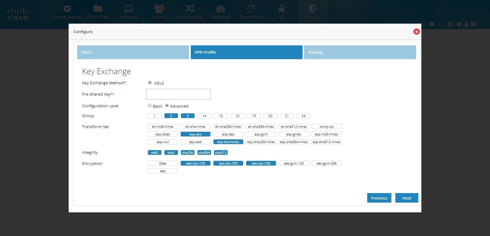
Figure 94 DMVPN Spoke Configuration (VPN Profile)
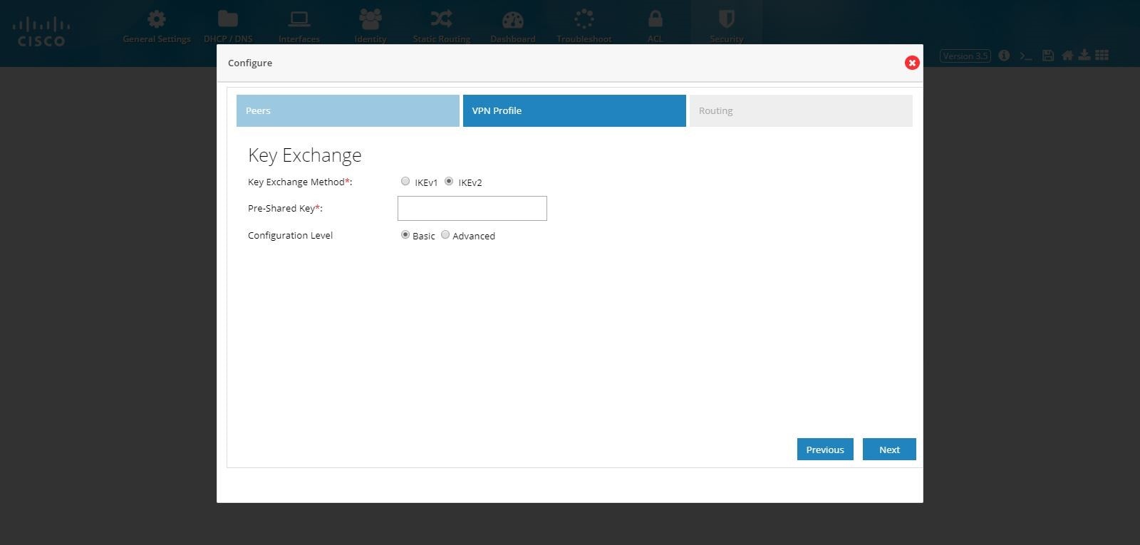
Figure 95 DMVPN Spoke Configuration (VPN Profile Advanced Options)
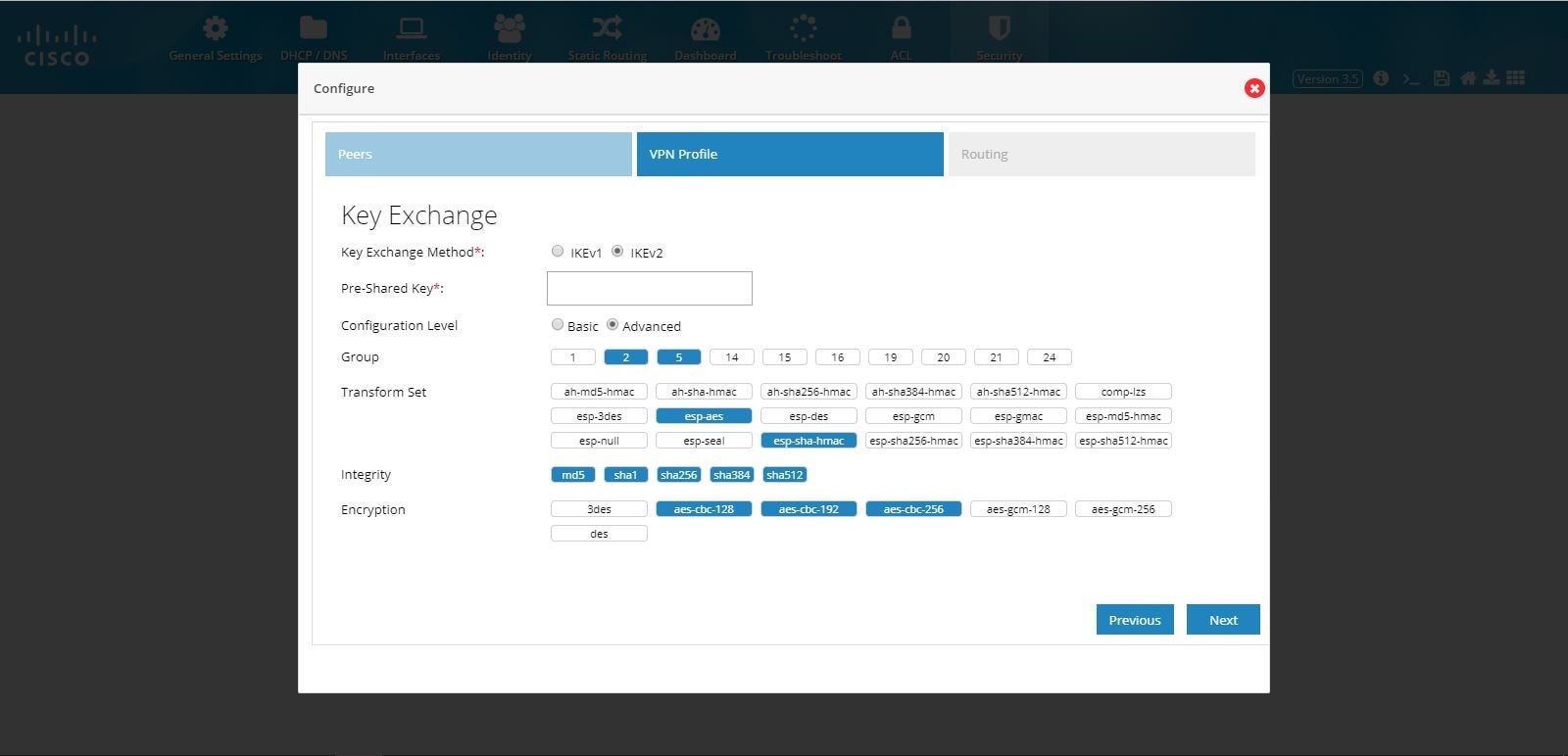
7.
Figure 96 DMVPN Spoke Configuration (Routing)
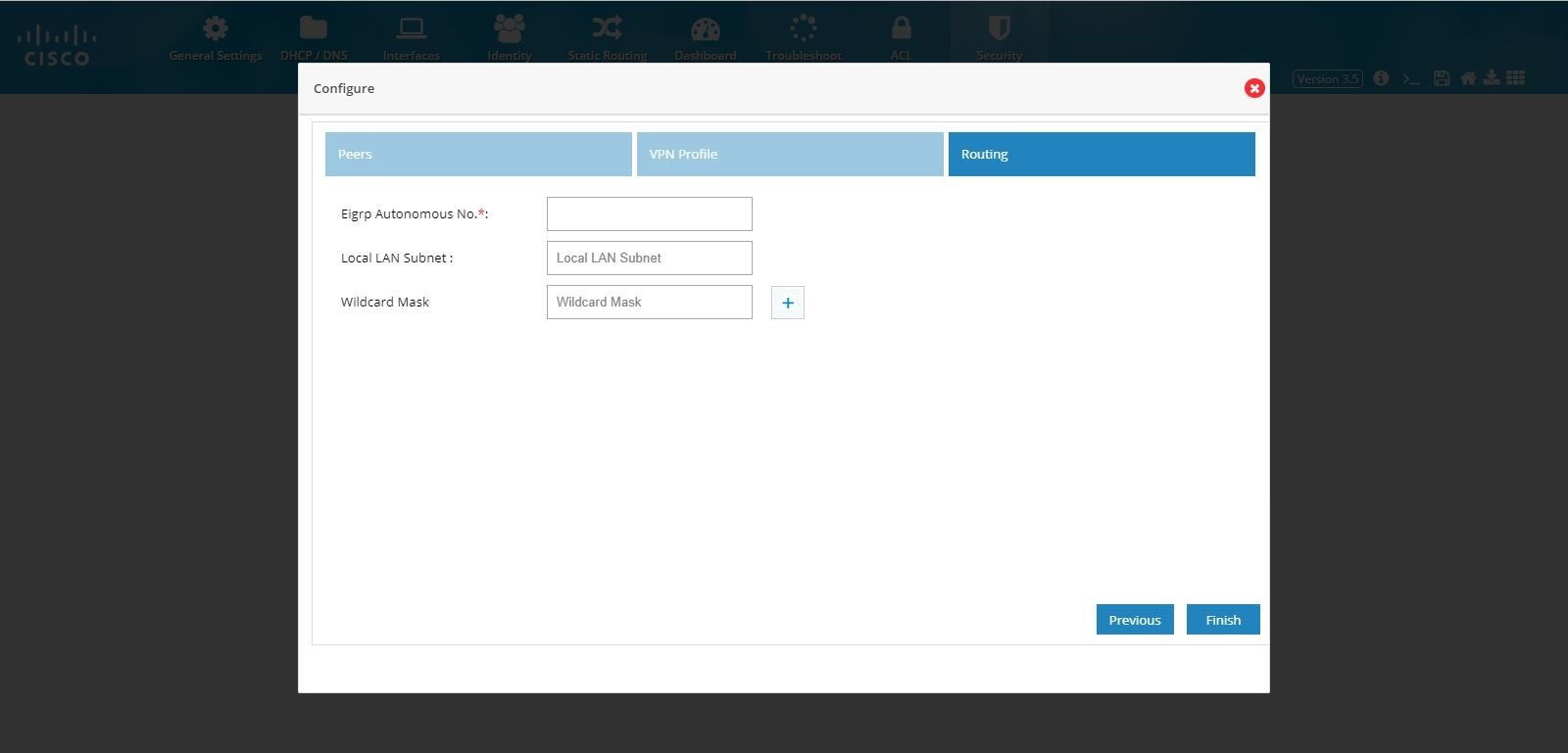
8.
Figure 97 DMVPN Spoke Configuration (Completed)
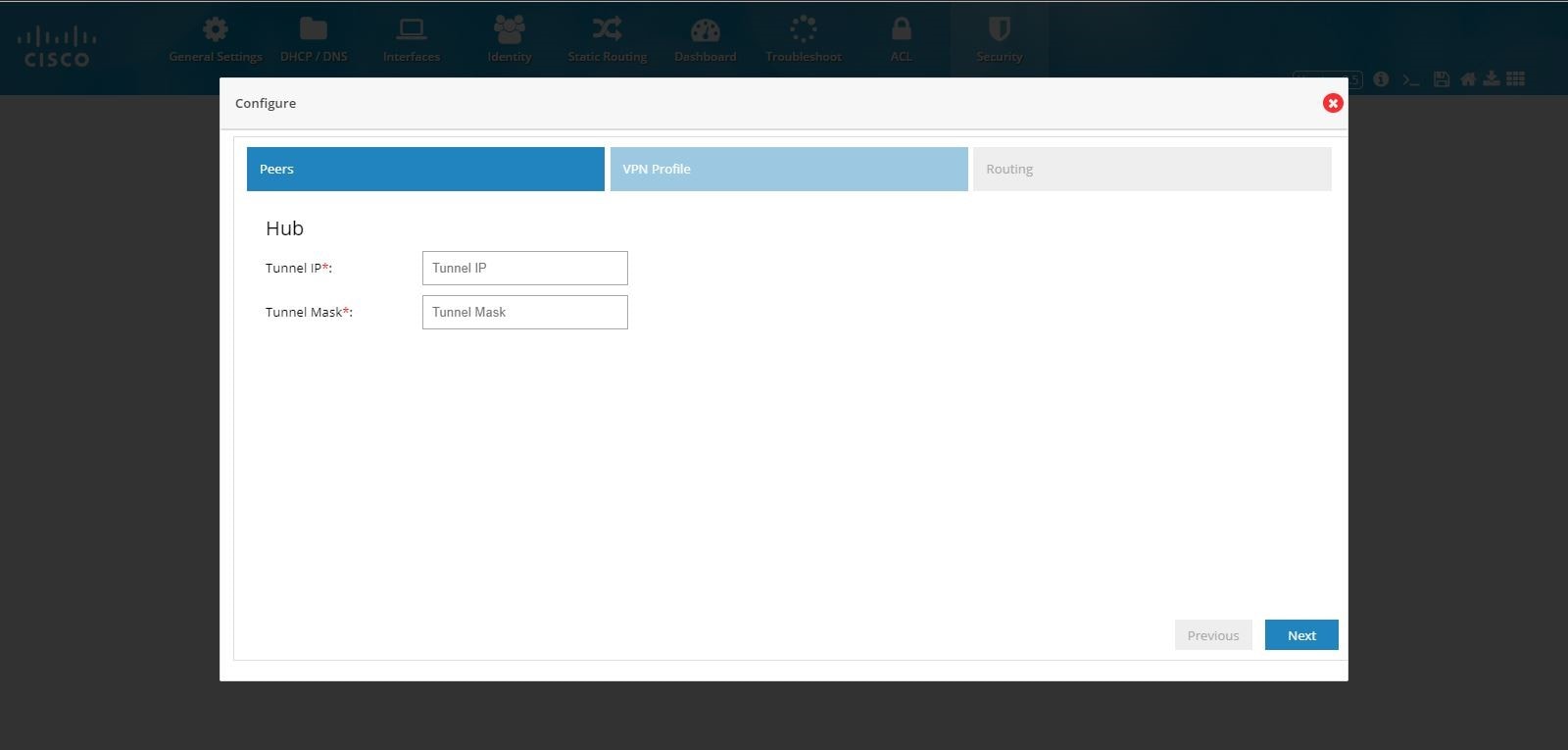
DMVPN Hub Configuration
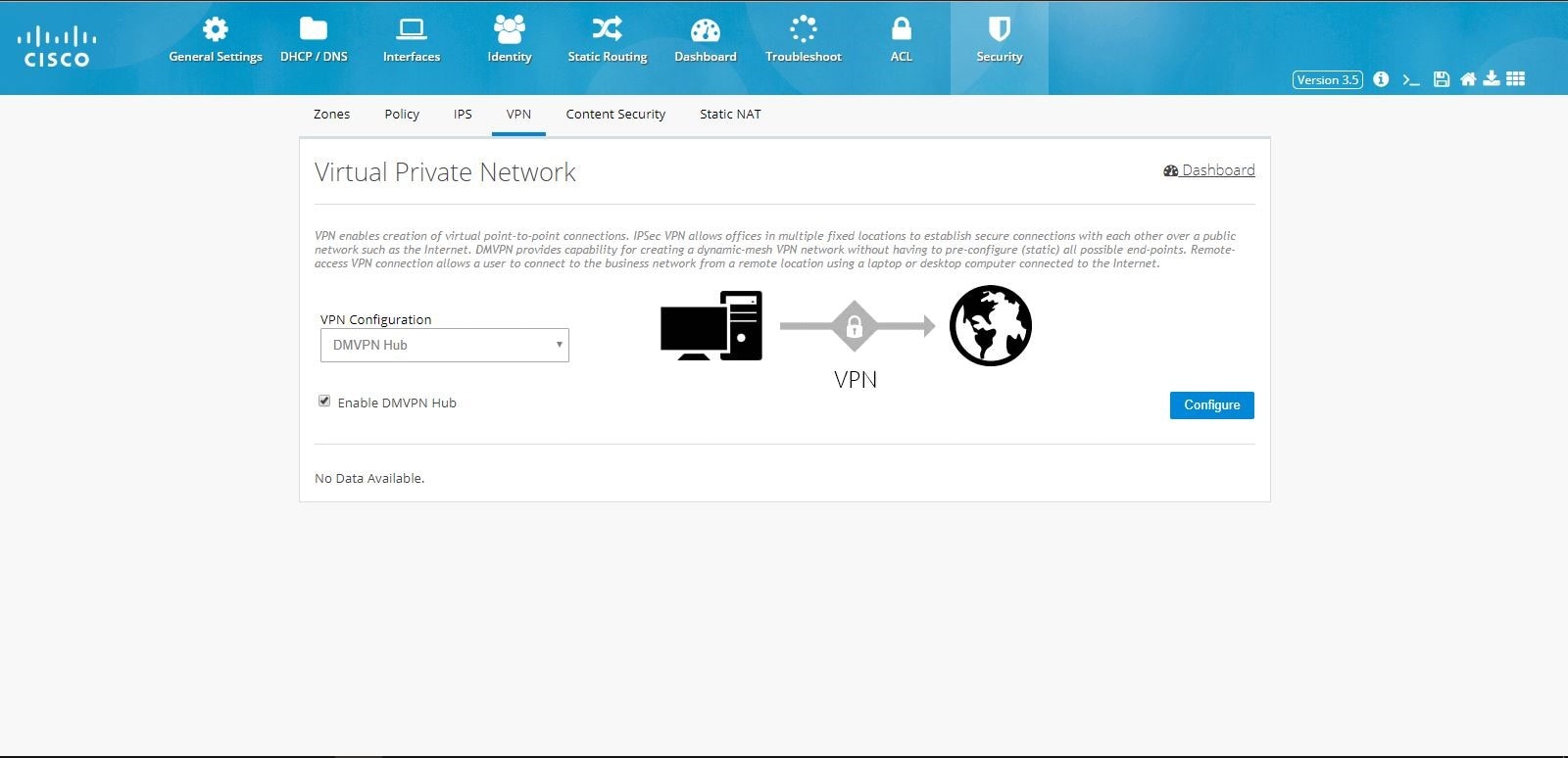
To configure DMVPN Hub:1.
2.
Figure 98 DMVPN Hub Configuration
3.
Figure 99 DMVPN Hub Configuration (VPN Peers)
4.
5.
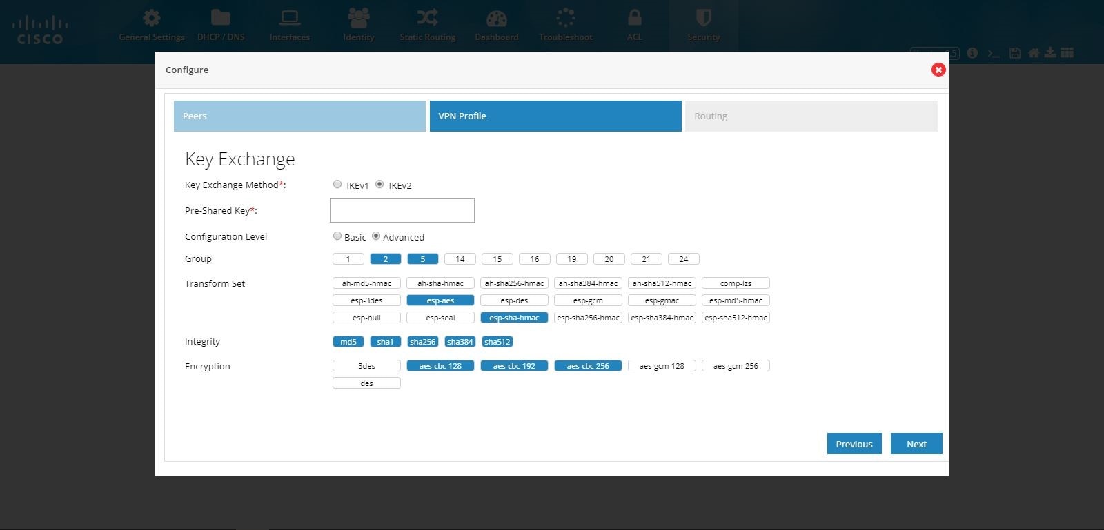
Figure 100 DMVPN Hub Configuration (VPN Profile)
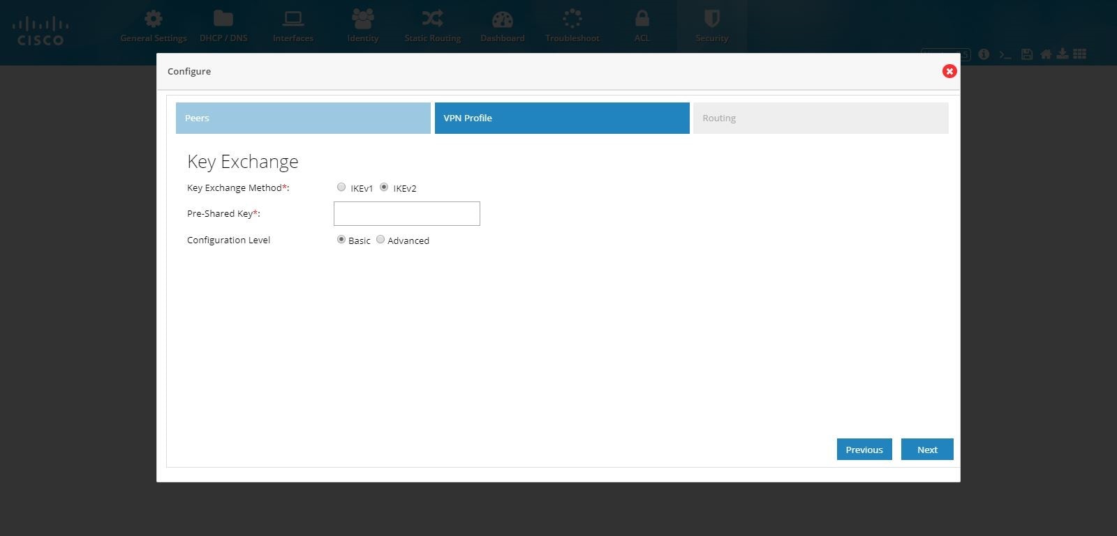
Figure 101 DMVPN Hub Configuration (VPN Profile Advanced Options)
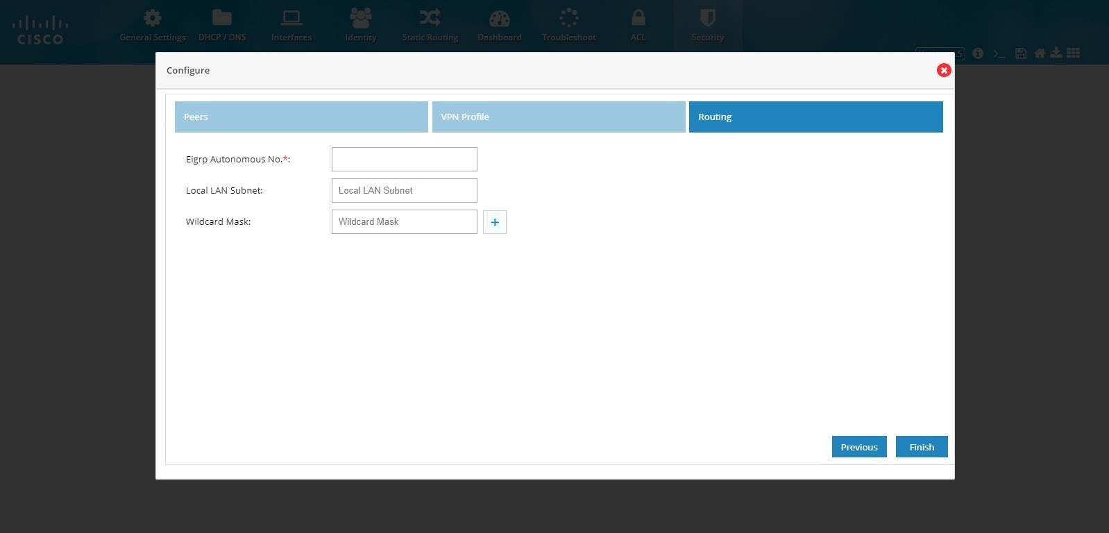
6.
7.
Figure 102 DMVPN Hub Configuration (Routing)
8.
Figure 103 DMVPN Hub Configuration (Completed)
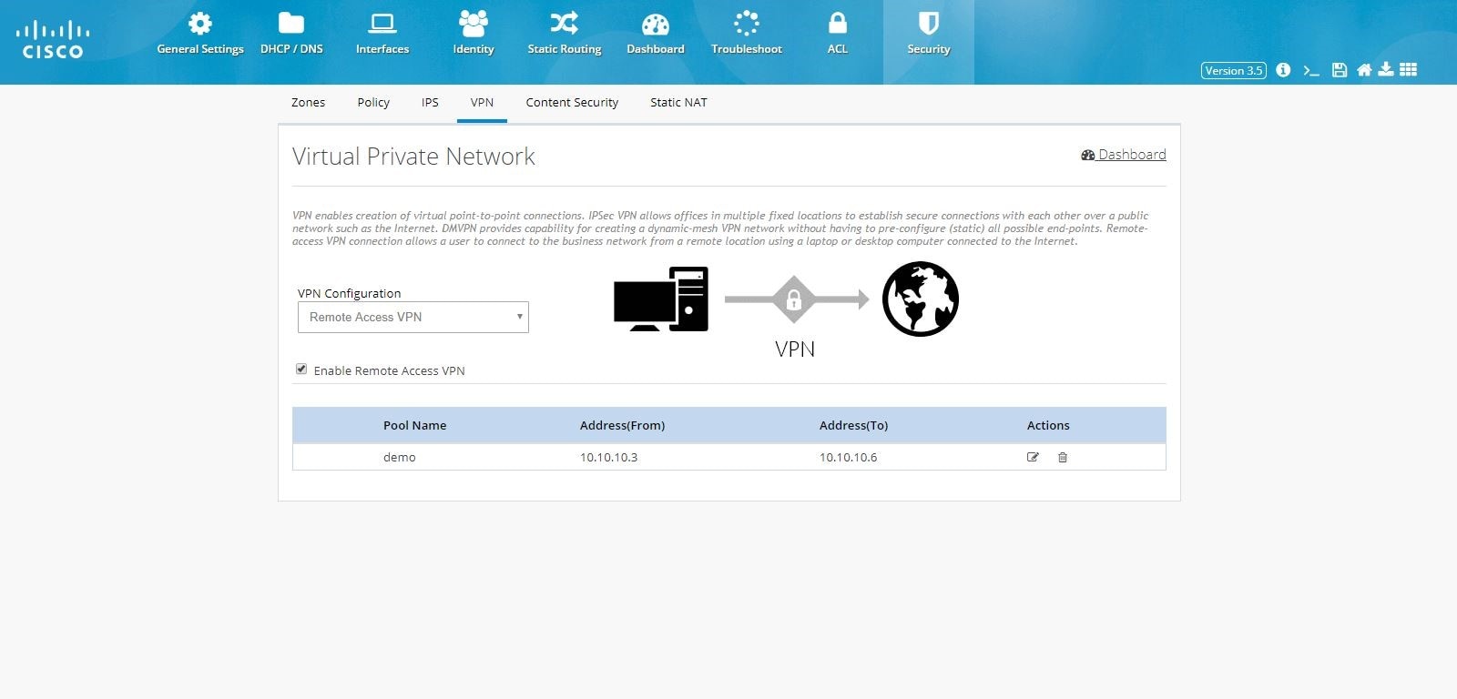
Remote Access VPN Configuration
To configure Remote Access VPN, perform these steps:1.
2.
Figure 104 Remote Access Configuration

3.
Figure 105 Remote Access Configuration (Pool)
4.
Note: By default, Remote Access VPN configuration supports only IKEv1 Key Exchange model and IP Sec enabled L2TP protocol.
Figure 106 Remote Access Configuration (VPN Profile)
5.
Figure 107 Remote Access Configuration (Mapping)
6.
Figure 108 Remote Access Configuration (Completed)
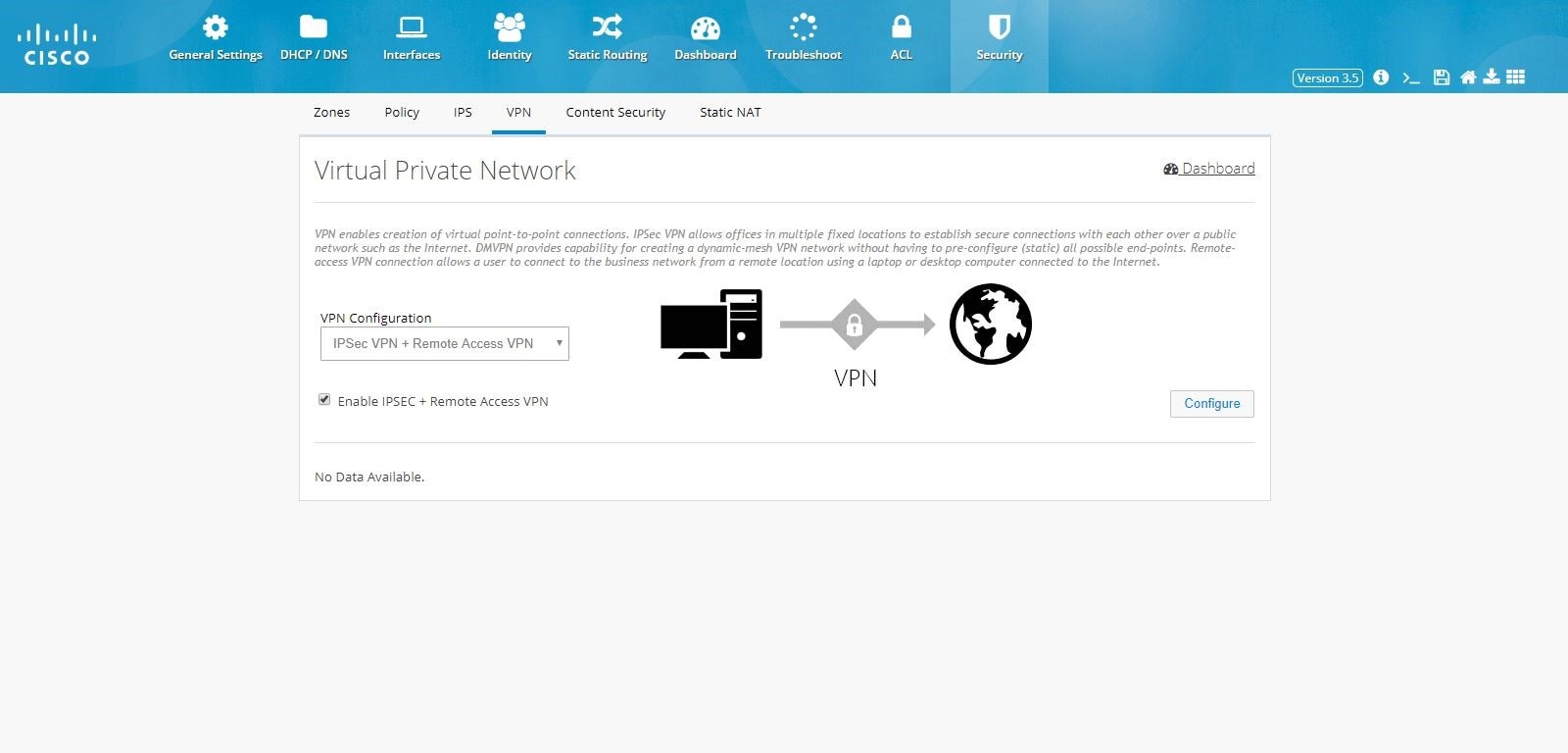
IPSec Multi-Site and Remote Access VPN Configuration Combination
To configure the combination of IPSec Multi-Site and Remote Access VPN configurations:1.
2.
Figure 109 IPSec Multi-Site and Remote Access Configuration Combination
3.
Figure 110 IPSec Multi-Site and Remote Access Configuration Combination (Tunnel)
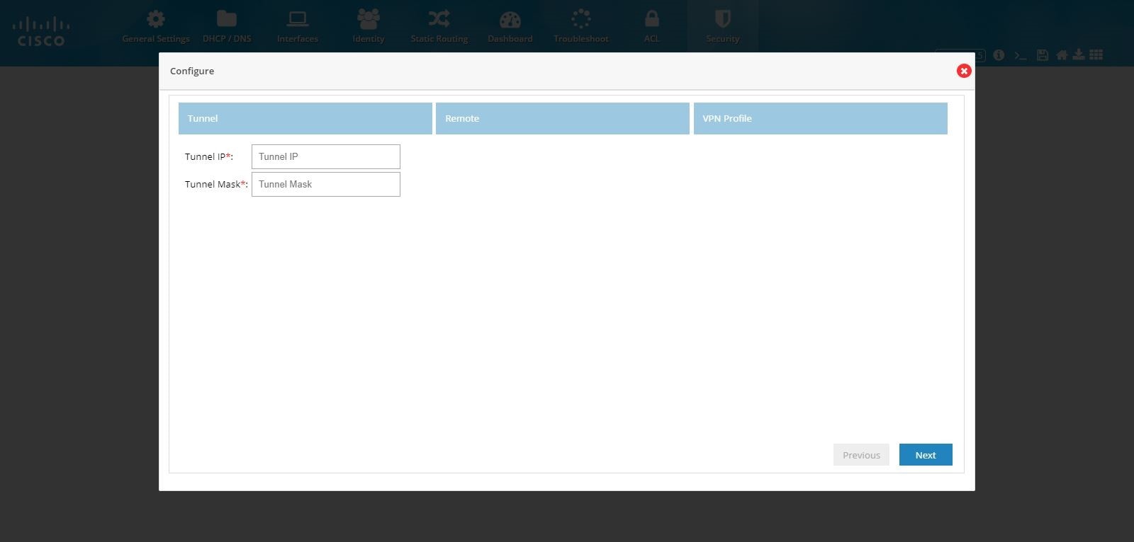
Note: By default, from configuring site end, all the LAN side networks are allowed to access the other end through VPN tunnel.
4.
Enter the pool information, Preshared Key, and Crypto Map Interface.
Figure 111 IPSec Multi-Site and Remote Access Configuration Combination (Remote)
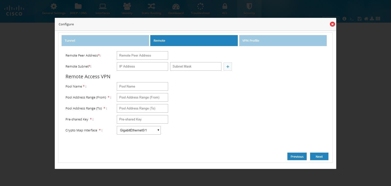
5.
Note: IKEv2 is the only key exchange method available.
Figure 112 IPSec Multi-Site and Remote Access Configuration Combination (VPN Profile)
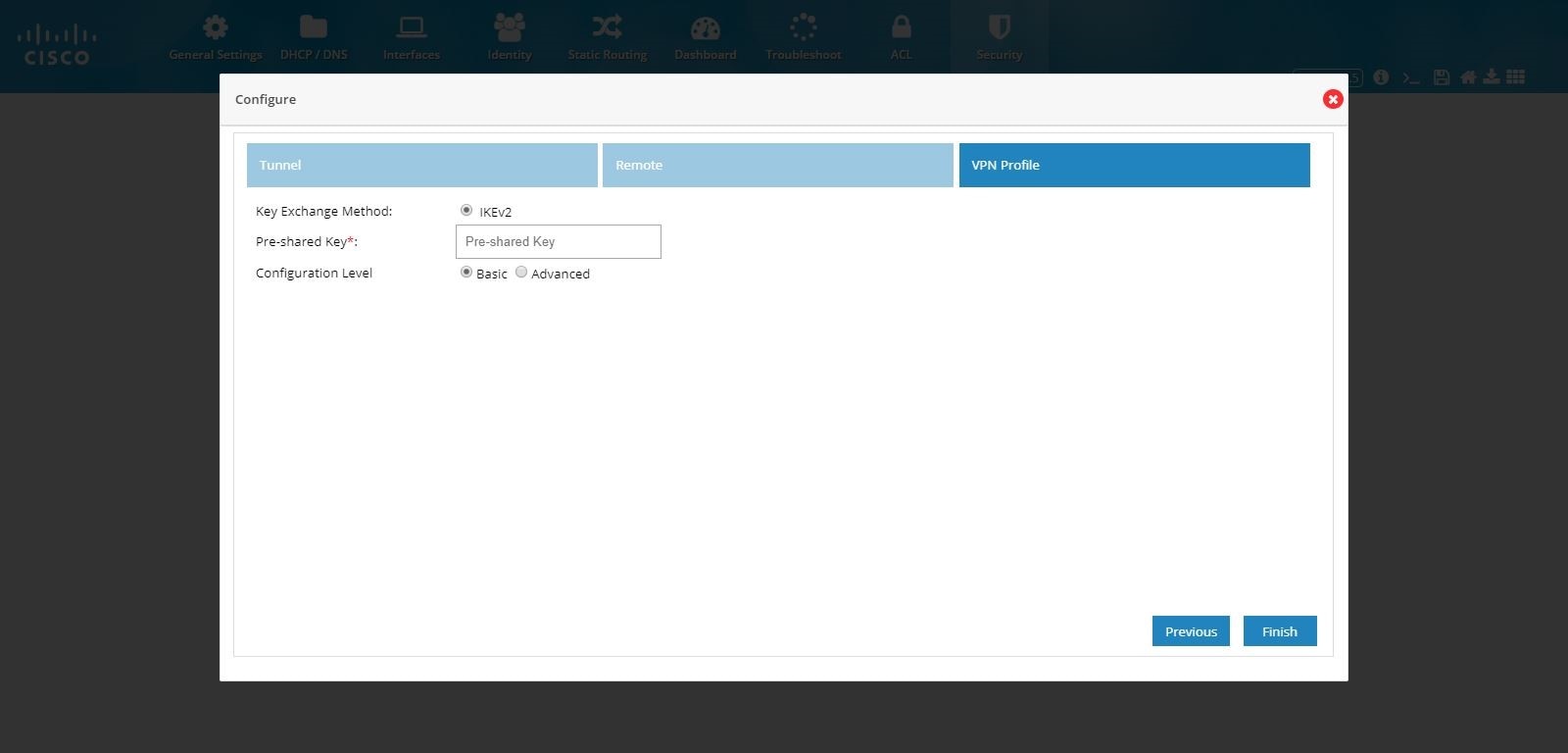
Figure 113 IPSec Multi-Site and Remote Access Configuration Combination (Advanced Options)

Note: If CCP Express is used to configure the Multi-Site VPN, ensure that both the ends are configured with CCP Express only. CCP Express internally uses the transform set as esp-aes, esp-sha-hmac and IKEv2 Proposal with encryption as 3des, integrity as md5 and Diffie Helman group as 2.
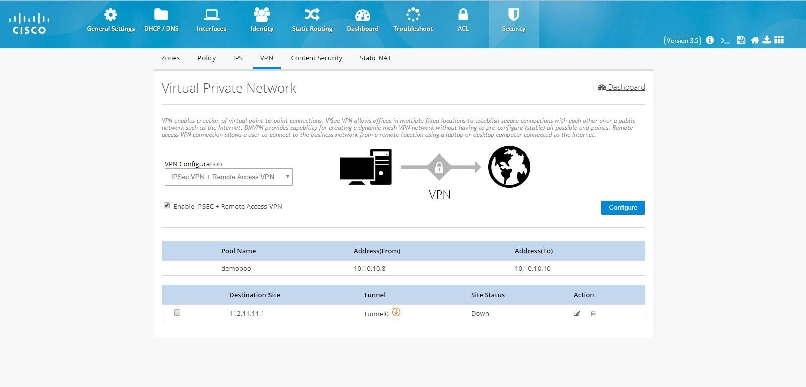
6.
Figure 114 IPSec Multi-Site and Remote Access Configuration Combination (Completed)
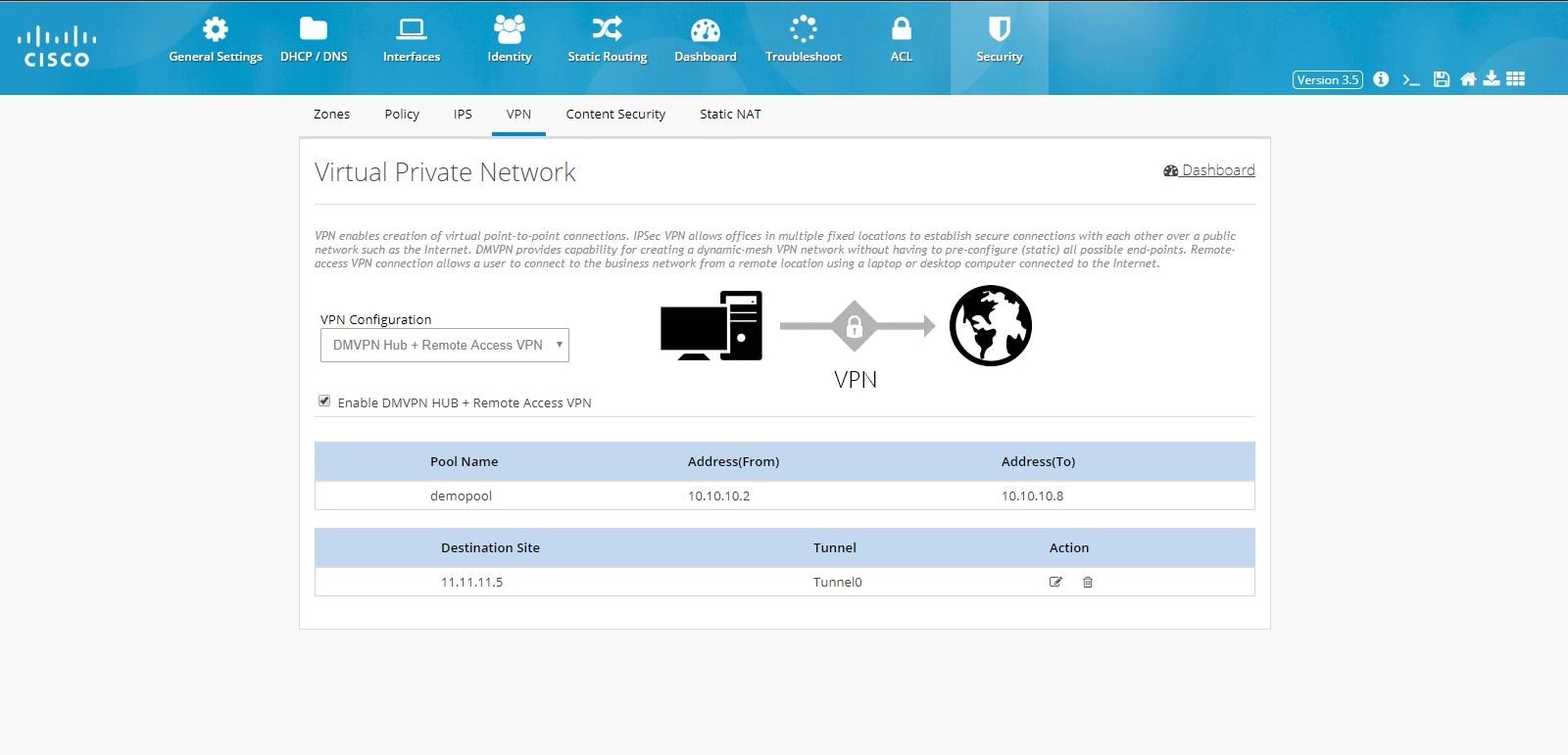
DMVPN Hub and Remote Access Configuration Combination
To configure the combination of DMVPN Hub and Remote Access VPN configurations:1.
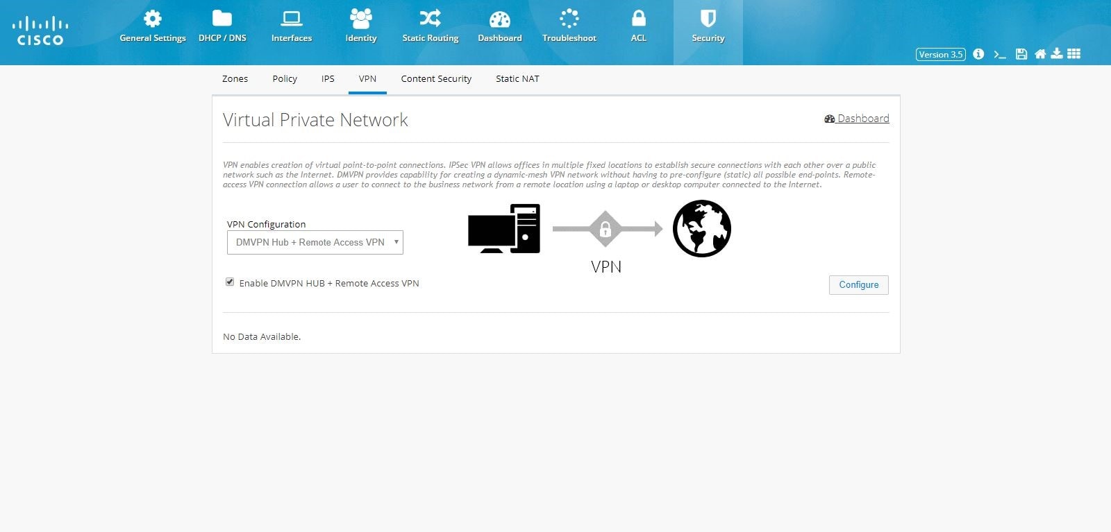
2.
Figure 115 DMVPN Hub and Remote Access Configuration Combination
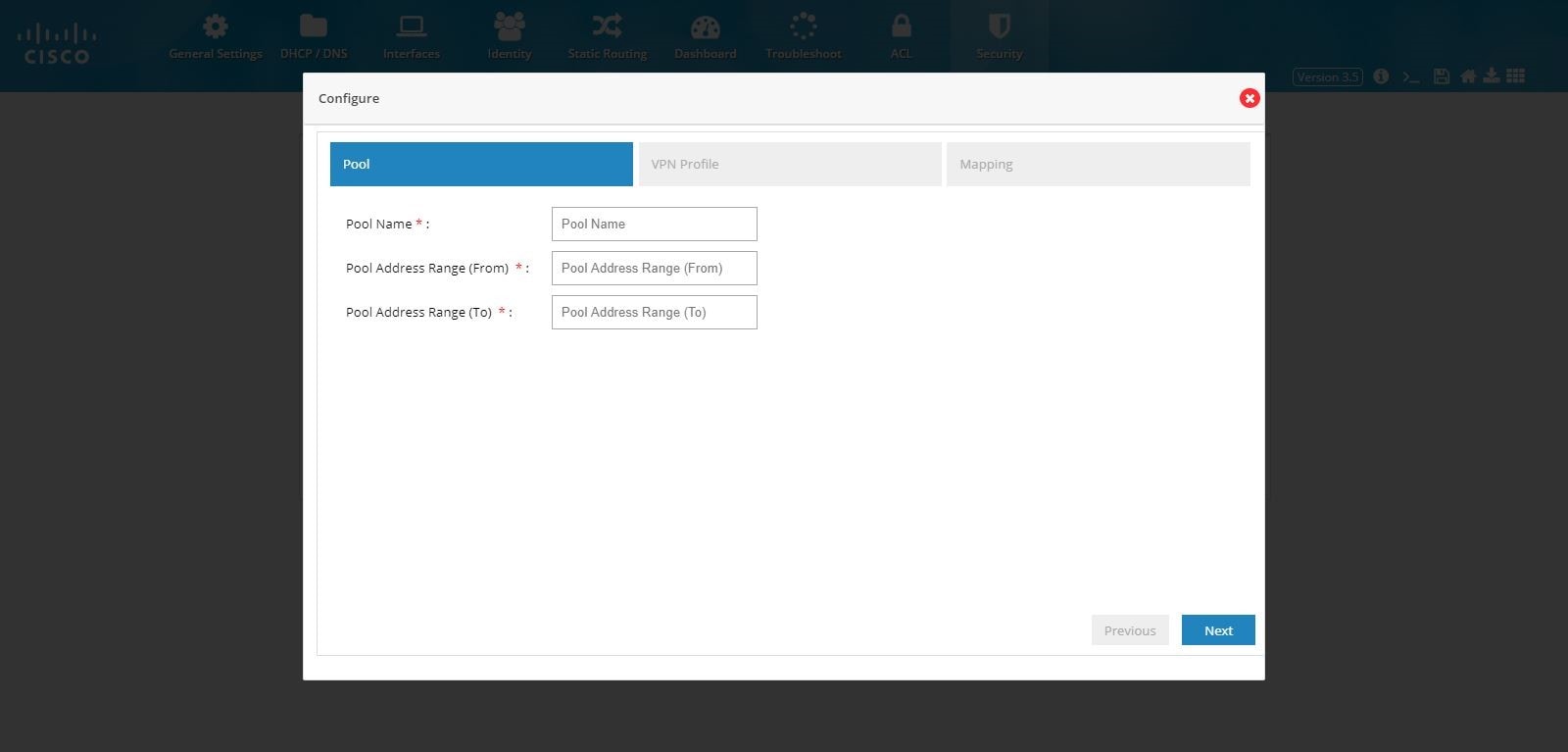
3.
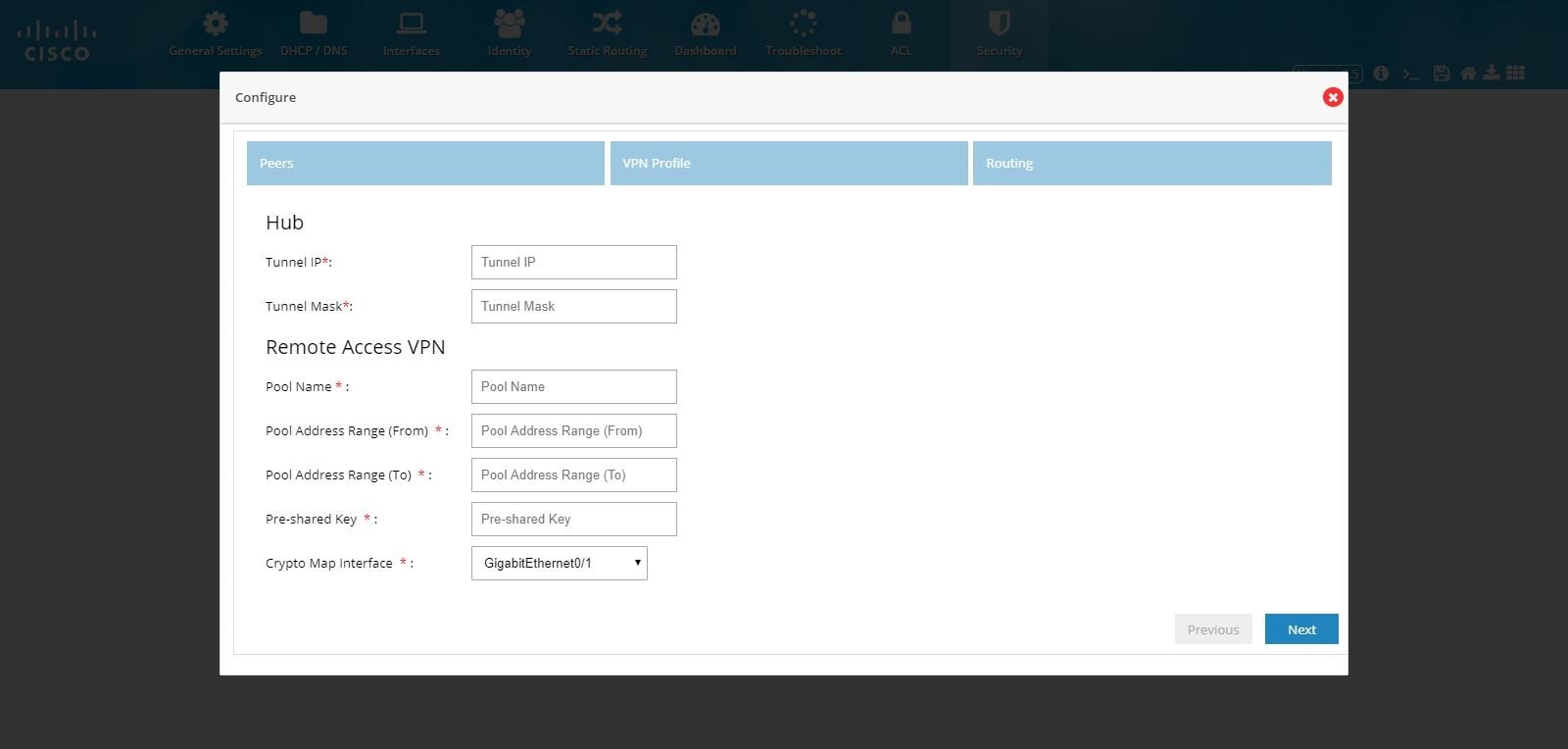
Enter the pool information, Preshared Key, and Crypto Map Interface.
Figure 116 DMVPN Hub and Remote Access Configuration Combination (VPN Peers)
4.
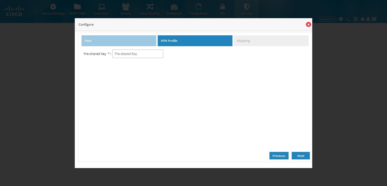
Note: IKEv2 is the only key exchange method available.
5.
Figure 117 DMVPN Hub and Remote Access Configuration Combination (VPN Profile)
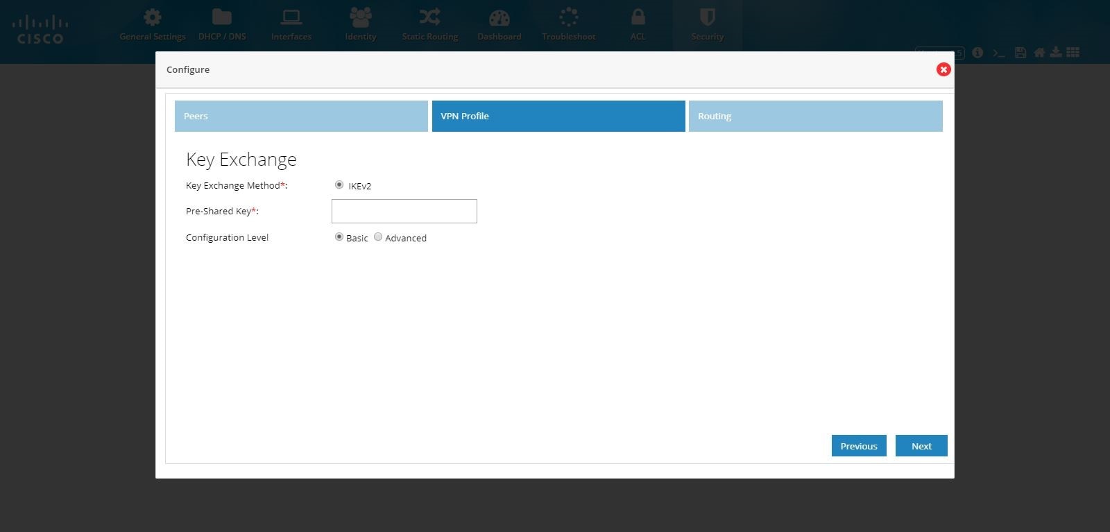
Figure 118 DMVPN Hub and Remote Access Configuration Combination (VPN Profile Advanced Options)
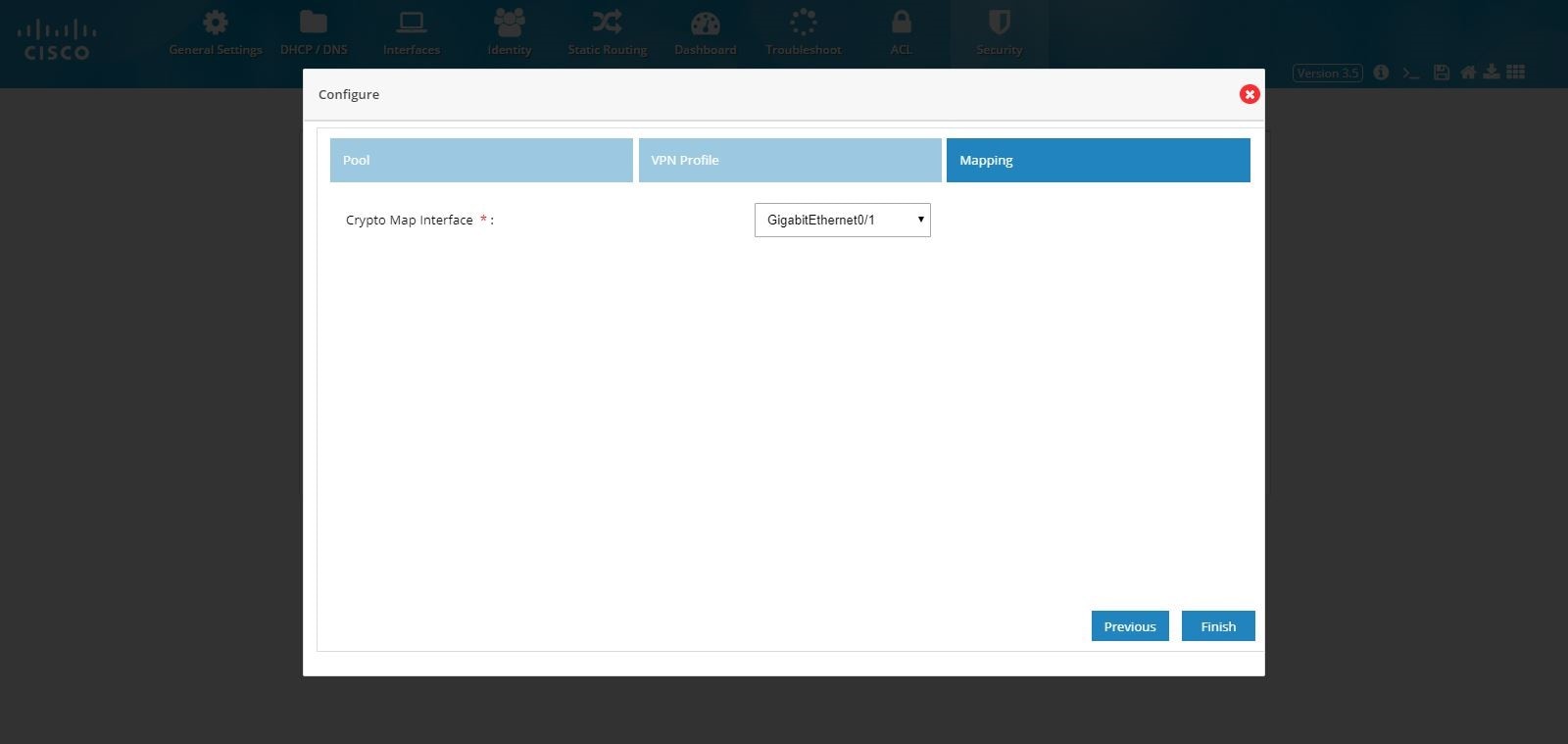
6.
7.
Figure 119 DMVPN Hub and Remote Access Configuration Combination (Routing)

8.
Figure 120 DMVPN Hub and Remote Access Configuration Combination (Completed)
Content Security
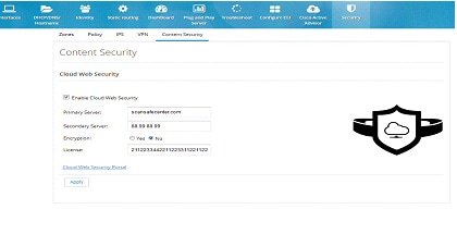
Cloud based 'Security as a Service’ (SecaaS) such as Cloud Web Security (CWS) is a scalable means to provide market-leading web security to quickly and easily protect the network from web-based threats, such as Malware, while saving bandwidth, money, and resources. CWS provides Anti-X functionality (anti-malware, anti-bot, anti-virus, and anti-phishing) on ISR-G2 itself without the need for expensive Security Appliances in branch, small offices.To configure content security, perform these steps:
1.
2.
3.
Figure 121 Content Security Page
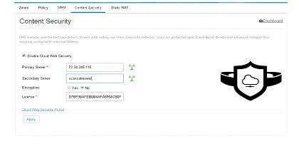
Edit Content Security
After CWS is fully configured and the tower is reachable, a green tower icon displays as shown in the screen below. Otherwise, the tower is displayed in red.Figure 122 Content Security Page
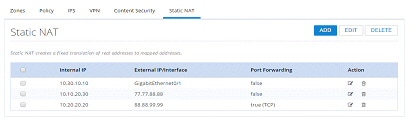
Static NAT
Static NAT creates a fixed translation of unregistered real address to mapped registered address. Also with port forwarding option, it is possible to open ports in response to inbound traffic for a specified service.To create a static NAT:
1.
Figure 123 Static NAT Page
2.
3.
4.
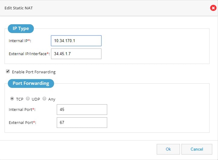
Figure 124 Edit Static NAT Page


No hay comentarios:
Publicar un comentario